
Practice Free VNX301 Exam Online Questions
Examine the exhibit below.
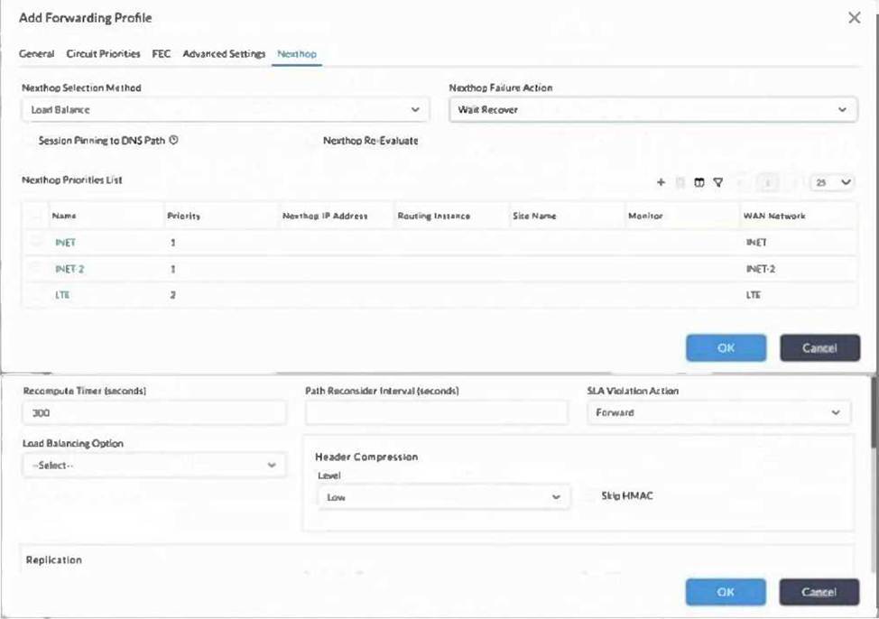
An SD-WAN administrator has configured Direct Internet Access (DIA) for INET and INET-2 and wants to use SaaS Application Monitoring and SD-WAN policies to steer certain applications to the best Internet path on a certain VOS device.
Which two statements are true regarding the configuration shown in the exhibit? (Choose two.)
- A . The VOS device will determine the optimal path out of INET and INET-2 using a proprietary algorithm.
- B . The VOS device will load balance the sessions across INET and INET-2 as long as they are both SLA-compliant.
- C . The VOS device will start using the LTE traffic if the INET circuit becomes unavailable.
- D . The VOS device will not drop the traffic if there are no SLA-compliant nexthops.
B, D
Explanation:
The correct answers are B and D. In the exhibit, the Next-Hop Selection Method is configured as Load Balance, and both INET and INET-2 have the same next-hop priority value of 1. Versa SD-WAN guidance states that load balancing between WAN paths is achieved by configuring at least two circuits with equal priority. Therefore, when both INET and INET-2 satisfy the SLA requirements, sessions can be load-balanced across those two internet circuits.
Option D is also correct because the exhibit shows SLA Violation Action: Forward. This means that if no next hop is SLA-compliant, the VOS device is still allowed to forward traffic instead of dropping it. This behavior is consistent with Versa SD-WAN traffic-steering concepts, where forwarding profiles define circuit or path priorities, connection methods, load-balancing behavior, and SLA handling for traffic that matches an SD-WAN policy.
Option A is incorrect because the exhibit does not use the Automatic next-hop selection method. Versa’s performance-based SaaS optimization uses monitoring metrics to select the best path when configured for automatic/performance-based selection, but this exhibit shows Load Balance instead.
Option C is not the best answer because LTE has lower priority 2 and would be considered only after the higher-priority INET and INET-2 paths are unavailable or unusable, not merely when one INET circuit fails.
During onboarding, Versa Director shows the first branch-connect notification for a new CPE, but no later staged branch-connect notification appears.
Which troubleshooting area should be investigated first?
- A . Versa Analytics log collector disk usage
- B . Data path or IPsec connectivity from the branch to the Controller
- C . LDAP authentication configuration on the tenant
- D . URL filtering database download status
B
Explanation:
The correct answer is B. Versa branch lifecycle notifications are generated at different stages of onboarding. The first notification indicates that the branch connected using factory-default configuration. After that notification, Versa Director pushes the staging configuration to the branch and requests a reboot. After rebooting with staging configuration, the branch should connect again to the Controller, and a later branch-connect notification should appear.
If this later staged connection notification does not appear, Versa’s troubleshooting guidance says to debug either the data path or IPsec connectivity from the branch to the Controller. This makes sense because the branch must have working transport reachability and IKE/IPsec establishment toward the Controller before it can continue the SD-WAN lifecycle.
Analytics disk usage, LDAP authentication, and URL filtering are not part of the branch staging control path. They may affect monitoring, user identity, or security inspection after the site is operational, but they do not explain why the branch stops after the initial factory-default onboarding notification.
During branch onboarding, you need to verify whether the Controller has sent branch-connect and branch-disconnect notifications to Versa Director.
Which CLI command should be used?
- A . show alarms
- B . show system storage
- C . show interfaces detail
- D . show cgnat acl info
A
Explanation:
The correct answer is A. Versa troubleshooting documentation states that after a branch device successfully establishes an IPsec connection to the Controller node, the Controller sends a notification to the Director node. To display the details of this notification, the documentation instructs administrators to issue the show alarms CLI command. It also provides examples using show alarms | match branchd | match br101 to view branch-connect and branch-disconnect events.
These alarm entries are valuable during onboarding because they show whether the branch reached the Controller, whether staging progressed, and whether the branch later disconnected. For example, branch lifecycle notifications include factory-default connection, staged connection, Stage 3 connection with WAN IP addresses, and branch disconnect events.
show system storage is useful for disk usage, show interfaces detail helps with link state, speed, duplex, and interface counters, and show cgnat acl info is used for CGNAT matching. None of those commands directly confirms branch lifecycle notifications between Controller and Director.
Examine the CLI output in the exhibit.
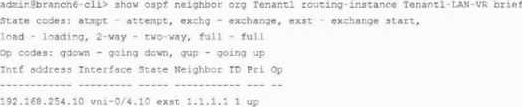
You are reviewing the OSPF adjacency on a VOS CPE, and the output is shown in the exhibit.
In this scenario, what is the probable cause of the OSPF adjacency issue?
- A . There is an OSPF area mismatch between the peers.
- B . There is an interface MTU mismatch between the OSPF peers.
- C . There is no bidirectional communication between the OSPF peers.
- D . There is a filter configured on the peer that is dropping 224.0.0.5 traffic.
B
Explanation:
The correct answer is B. The exhibit shows the OSPF neighbor in the exst state, which means Exchange Start. Versa documentation lists the OSPF neighbor state codes and identifies exst as “exchange start,” followed by exchange, loading, and full. In normal OSPF adjacency formation, neighbors progress through initialization and two-way communication before they negotiate database exchange. If the neighbor becomes stuck in ExStart or Exchange, a common and highly probable cause is an MTU mismatch between the two OSPF peers. During database description packet negotiation, the peers must agree on parameters that allow LSDB exchange; an MTU mismatch can prevent the adjacency from advancing to Full.
Option A is less likely because an area mismatch usually prevents the neighbor relationship from forming correctly rather than leaving it stuck in ExStart.
Option C is also incorrect because the neighbor has already progressed beyond early states, which indicates that bidirectional communication has occurred.
Option D is not the best answer because dropping OSPF multicast 224.0.0.5 would typically prevent discovery or keep the adjacency in an earlier state, not specifically in ExStart. Therefore, the probable cause is an interface MTU mismatch.
Examine the exhibit below.
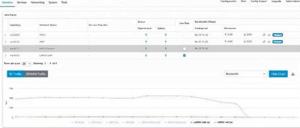
As an administrator of a Versa Secure SD-WAN deployment, you are asked to find the current bandwidth of each WAN circuit used for SD-WAN connectivity in a branch, but Versa Director is not displaying any information for the WAN circuits.
In this scenario, what should be done to get the graph populated for all WAN circuits?
- A . Refresh the page to get the graphs populated in the dashboard.
- B . Select Live Data for all WAN circuits in the dashboard.
- C . Select Live Data for MPLS circuits alone.
- D . Unselect Live Data for the INET circuit and select it again.
B
Explanation:
The correct answer is B. In the exhibit, Versa Director shows multiple branch interfaces and a Live Data column. To populate the bandwidth graph with current real-time statistics for all WAN circuits, Live Data must be selected for each WAN circuit that should be monitored. Versa documentation states that from a Director node, administrators can monitor VOS devices, provider organizations, tenants, events, and alarms. It also explains that Versa Director, together with Versa Analytics, can poll VOS devices in real time to provide visibility into what is happening on those devices and to assist with troubleshooting.
Because the requirement is to find the current bandwidth of each WAN circuit, simply refreshing the page is not enough. Refreshing only reloads the dashboard; it does not enable real-time polling for interfaces that are not selected. Selecting Live Data only for MPLS circuits would populate only MPLS-related data and would not satisfy the requirement for all WAN circuits. Unselecting and reselecting only the INET circuit affects only that one circuit. Therefore, the correct operational step is to enable Live Data for all WAN circuits shown in the branch interface dashboard.
A branch uses a template variable for the WAN VLAN ID. During deployment, Branch-A receives VLAN 100 and Branch-B receives VLAN 200 from device bind data while using the same template.
Which statement is correct?
- A . This is expected because template variables allow unique per-device values.
- B . This is impossible because all devices using a template must share identical VLAN IDs.
- C . The device template must be duplicated for each branch.
- D . The Controller automatically rewrites VLAN IDs after IPsec comes up.
A
Explanation:
The correct answer is A. Versa template-based provisioning is designed to separate common configuration from site-specific values. A device template can define common interface, service, routing, and SD-WAN behavior, while variables and device bind data provide unique values for each appliance. This allows the same template to be reused across many branches while assigning different WAN IP addresses, gateways, VLAN IDs, circuit names, or other per-site parameters during onboarding.
In this scenario, Branch-A and Branch-B use the same template but receive different WAN VLAN IDs from bind data. That is normal and expected in a scalable SD-WAN deployment. Without variables, administrators would need to create a separate template for every site, which would be operationally inefficient and increase configuration drift.
The Controller does not automatically rewrite VLAN IDs after IPsec comes up; VLAN IDs must be part of the generated device configuration. It is also not required to duplicate the device template for each branch. The correct Versa design is reusable templates plus unique bind-data values.
A branch has correct underlay speed and no asymmetric SD-WAN paths, but users still report packet loss during large transfers. You suspect QoS shaping is dropping traffic.
Which command is most appropriate to verify interface-level CoS drops?
- A . show class-of-services interfaces detail interface-name
- B . show alarms last-n 10
- C . show system uptime
- D . show cgnat tenants
A
Explanation:
The correct answer is A. Versa throughput troubleshooting documentation includes a specific section titled Check that Packets Are not Dropped by CoS. It states that if a CoS shaper or rate limiter is configured on the VOS device, it may drop packets when traffic exceeds the configured shaping rate. To check whether CoS is dropping packets, Versa recommends commands including show class-of-services interfaces brief and show class-of-services interfaces detail interface-name.
The detailed interface output displays traffic statistics such as TX packets, TX packets dropped, TX bytes, TX bytes dropped, and per-traffic-class drops. This is exactly the evidence needed to confirm whether shaping or QoS enforcement is causing the observed loss.
show alarms last-n 10 may reveal major events but will not provide per-interface CoS drop counters. show system uptime only indicates how long the system has been running. show cgnat tenants is relevant for NAT state and tenant CGNAT resources, not QoS drops.
Examine the exhibit below.
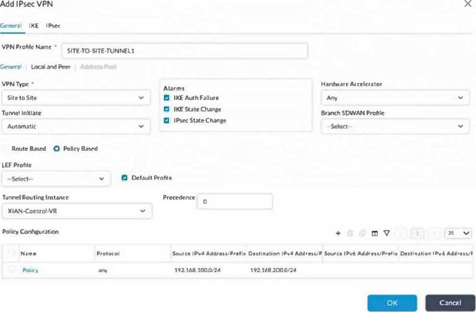
You are configuring an IPsec tunnel towards a non-SD-WAN site over the INET Transport-VR. The site IP address is 10.1.1.1. This tunnel is for traffic between the 192.168.100.0/24 and the 192.168.200.0/24 LAN networks. The tunnel does not establish.
Referring to the exhibit, which statement is correct?
- A . The Tunnel Routing Instance is incorrect.
- B . The Routing Instance should be changed to global.
- C . A precedence higher than 0 needs to be set.
- D . The Policy Configuration is missing an additional policy with the subnets swapped.
A
Explanation:
The correct answer is A. The exhibit shows that the IPsec VPN is being configured with Tunnel Routing Instance: XIAN-Control-VR. However, the question states that the tunnel is toward a non-SD-WAN site over the INET-Transport-VR. For a site-to-site IPsec tunnel, the tunnel routing instance must match the routing instance used to reach the peer public IP address. In this case, the remote non-SD-WAN peer is 10.1.1.1, and the intended underlay transport is INET-Transport-VR, not the Control VR.
Versa troubleshooting documentation explains that routing instances are used to define where traffic is sourced and forwarded. For example, configuration examples select routing instances when enabling services or initiating tests, and traffic must use the correct WAN or transport routing instance to reach the remote endpoint. Versa branch troubleshooting also emphasizes that after transport connectivity is available, the branch establishes IKE-based IPsec connectivity; if that connectivity fails, the IPsec-related interface remains down.
Changing the routing instance to global would not be correct because the intended path is specifically INET-Transport-VR. A higher precedence value is not required to establish the tunnel. The policy selector shown already defines local-to-remote interesting traffic, and the key failure is the incorrect tunnel routing instance.