
Practice Free NSE5_FSW_AD-7.6 Exam Online Questions
Which three are valid actions that a FortiSwitch access control list (ACL) can apply to matching traffic? (Choose three answers)
- A . Assign the VLAN ID
- B . Quarantine devices
- C . Traffic processing
- D . Set outer VLAN tags
- E . QoS
C, D, E
Explanation:
According to theFortiSwitchOS 7.6 Administration Guideand theNSE 5 FortiSwitch 7.6 Administrator Study Guide, Access Control Lists (ACLs) are used to perform multiple actions on matching traffic as it passes through the switch pipeline. The documentation explicitly categorizes these valid actions into three distinct functional groups: Traffic processing, QoS (Quality of Service), andVLANmodifications.
Traffic Processing (Option C): This is a primary category of ACL actions. It includes operations that dictate how a frame is physically handled or monitored. Valid specific actions under this category includedrop (discarding the packet), count (incrementing a packet counter for statistics), redirect (sending the packet to a specific interface or CPU queue), andmirror (copying the traffic to a monitor port ).
QoS (Option E): The QoS category allows the switch to manage traffic prioritization and bandwidth. ACLs can be configured toset the egress queue (assigning a frame to one of the eight priority queues), remark CoS (Class of Service) orDSCP (Differentiated Services Code Point) values in the frame header, and applypolicersfor rate limiting.
VLAN / Set outer VLAN tags (Option D): Under the VLAN category, the most notable action is the ability toset outer VLAN tagson frames. This is particularly useful in scenarios involving Q-in-Q tunneling or service provider environments where a secondary tag is required for transport across a managed fabric.
It is important to note thatAssign the VLAN ID (Option A) is typically a function ofNAC (Network Access Control) orDynamic VLAN Assignmentrather than a standard ACL action; within an ACL context, vlan-id is primarily used as aclassifier (to match traffic) rather than an action.Quarantine devices (Option B) is a high-level security response triggered by the FortiGate NAC engine and is not a direct action available within the FortiSwitch ACL configuration menu.
Which QoS mechanism maps packets with specific class of service (COS) or Differentiated Services Code Point (DSCP) markings to an egress queue? (Choose one answer)
- A . Classification for ingress traffic
- B . Queuing for egress traffic
- C . Policing for ingress traffic
- D . Shaping for egress traffic
B
Explanation:
According to theFortiSwitchOS 7.6 Administration Guideand theFortiSwitch 7.6 Study Guide, Quality of Service (QoS) on a FortiSwitch involves several distinct stages to manage traffic priority and bandwidth. The specific process of taking identified packets and placing them into a specific priority buffer for transmission is known asQueuing.
On FortiSwitch, when a frame enters an ingress port, it is first classified based on its incomingCoS (Layer 2) orDSCP (Layer 3) markings.2However, it is theQueuing for egress traffic (Option B) mechanism that dictates which of the eight available hardware queues the frame will reside in before it is sent out of the destination port. The switch uses a mapping table (such as a CoS-to-queue or DSCP-to-queue map) to ensure that high-priority traffic, like voice or video, is placed in a higher-priority queue to minimize latency and jitter.
Regarding the other options: Classification (Option A) is the initial identification of the packet’s priority but does not perform the physical mapping to a buffer.Policing (Option C) is an ingress mechanism used to drop or remark traffic that exceeds a defined rate.Shaping (Option D) is an egress mechanism that smooths out traffic bursts by delaying packets but is separate from the initial queue assignment. Therefore, the act of mapping specific markings to an egress queue is a fundamental function of the queuing mechanism.
Refer to the exhibits.
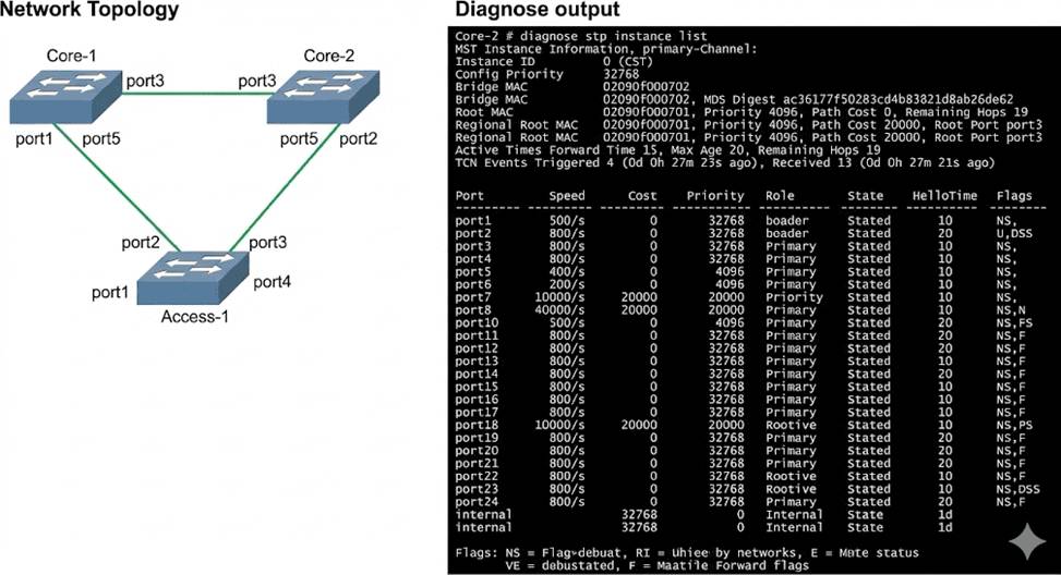
Three FortiSwitch devices in standalone mode are interconnected. The CLI command diagnose stp instance list is executed on Core-2.
Based on the output shown in the exhibit, what can you conclude about Core-2? (Choose one answer)
- A . Core-2 has received Bridge Protocol Data Unit (BPDU) from the root bridge.
- B . Core-2 is the designated bridge for all VLANs.
- C . Core-2 is blocking all ports in the Spanning Tree Protocol (STP) topology.
- D . Core-2 provides an alternate path to the root bridge.
A
Explanation:
According to theFortiSwitchOS 7.6 Administration Guideand theFortiSwitch 7.6 Study Guide, the output of the diagnose stp instance list command provides critical information about the Spanning Tree Protocol (STP) state of a switch within a given instance. In the provided exhibit, the output forInstance ID 0 (CST) onCore-2shows several key indicators of its role and connectivity within the STP
topology.
First, the output explicitly identifies aRootbridge with MAC address 02090f000701 and a priority of 4096. Core-2 itself has a MAC address of 02090f000702 and a priority of 32768. Because Core-2 knows the MAC address and priority of the Root bridge, it must have received this information via Bridge Protocol Data Units (BPDUs). Furthermore, the port table shows thatport3on Core-2 has been assigned the role of ROOT and is in the FORWARDING state. In STP/RSTP, a Root Port is the port on a non-root switch that has the lowest path cost to the root bridge. To elect a Root Port and maintain its state, the switch must continuously receive BPDUs from the root bridge (or a bridge closer to the root) on that port.
Option B is incorrect because Core-2 has aRoot Port, which is only present on non-root bridges.
Option C is incorrect because ports 1, 2, 4, 5, and the internal port are all in the FORWARDING state.
Option D is incorrect as the output does not show any ports in an ALTERNATE role; all active ports are either ROOT or DESIGNATED. Therefore, the most accurate conclusion is that Core-2 has successfully received BPDUs to identify the root and determine its own port roles.
Exhibit.
You need to manage three FortiSwitch devices using a FortiGate device. Two of the FortiSwitch devices initiated a reboot after the authorization process. However, the FortiSwitch device with the configuration shown in the exhibit. did not reboot All three devices completed FortiLink manage-ment authorization successfully.
Why did the FortiSwitch device shown in the exhibit not reboot to complete the authorization pro-cess?
The management mode was set to use FortiLink mode.
- A . Switch auto-discovery is enabled.
- B . The management mode was set to use FortiLink mode.
- C . The FortiSwitch device is scheduled to reboot as part the authorization process
- D . The system time is not in-sync and is using a non-default value
B
Explanation:
Regarding the scenario where a FortiSwitch did not reboot after the authorization process while the other devices did, the most likely cause, given the configuration settings in the exhibit, is:
The management mode was set to use FortiLink mode (Option B): If the FortiSwitch was already configured to use FortiLink for its management mode, it may not require a reboot to complete the authorization process as its management interface settings are already aligned with FortiLink requirements. This is unlike switches that might be transitioning from a standalone or another management mode, which would typically require a reboot to apply new management settings fully.
Reference: FortiLink mode specifically tailors FortiSwitch to be managed via a FortiGate device, integrating its operation into the wider security fabric without needing a reboot if it is already set to this mode before authorization. This contrasts with other management modes where transitioning to FortiLink could necessitate a system restart to initialize the new configuration.