
Practice Free NSE5_FSW_AD-7.6 Exam Online Questions
An administrator must deploy managed FortiSwitch devices in a remote location where multiple VLANs must be used to segment devices. No layer 3 switch or router is present at the site, and the only WAN connectivity is an ISP-provided router connected to the public internet.
Which two components are required to enable VLAN segmentation across this remote site? (Choose two answers)
- A . FortiGate and FortiSwitch configured with VXLAN to tunnel VLANs over the WAN
- B . A layer 3 router at the remote location to handle inter-VLAN routing
- C . A FortiSwitch model that supports VXLAN hardware acceleration
- D . FortiSwitch and FortiGate devices configured with IPsec interfaces
- E . FortiGate with a layer 3 interface to terminate the VXLAN overlay
A, E
Explanation:
According to theFortiOS 7.6 Administration Guideand theFortiSwitch 7.6 FortiLink Guide, deploying managed switches over a Layer 3 underlay―such as the public internet―requires a specific tunneling mechanism to bridge Layer 2 broadcast domains. Traditional FortiLink relies on a direct Layer 2 connection; however, for remote sites, FortiLink over VXLANis the standard solution.
FortiLink over VXLAN (Option A): Virtual Extensible LAN (VXLAN) is used to encapsulate Layer 2 Ethernet frames into Layer 3 UDP packets, allowing VLAN-tagged traffic to traverse an ISP’s routable network. This enables the FortiGate to manage remote FortiSwitch "islands" as if they were locally connected, maintaining full VLAN segmentation across the WAN.
Layer 3 Termination (Option E): The FortiGate acts as theVirtual Tunnel Endpoint (VTEP). It must have a reachable Layer 3 interface (such as a WAN port with a public IP or an IPsec tunnel interface) to terminate the VXLAN overlay. Once the VXLAN tunnel is terminated at the FortiGate, the encapsulated VLAN traffic is extracted, and the FortiGate can perform inter-VLAN routing and security inspection.
Regarding the incorrect options:
Option B is incorrect because the FortiGate at the central site handles the routing, eliminating the need for a local L3 device.
Option C is a performance consideration but not a functional requirement for basic connectivity.
Option D is often used for security to encrypt the underlay, but IPsec alone does not provide the Layer 2 extension capabilities required for VLAN segmentation; VXLAN is the specific component that handles the MAC-in-UDP encapsulation.
Refer to the exhibit.
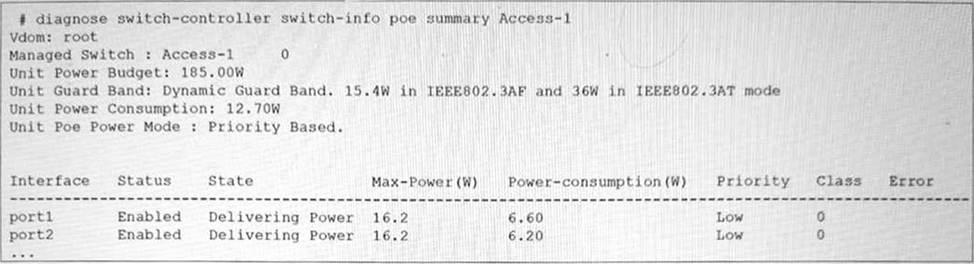
The FortiSwitch CLI output of the diagnose switch-controller switch-info poe summary command for the switch Access-1 is shown. It shows that two ports have Power over Ethernet (PoE) enabled and are already in use.
What is the most important consideration if you want to connect additional PoE devices to FortiSwitch? (Choose one answer)
- A . All plugged devices use the same PoE standard: 802.3af/at.
- B . The FortiSwitch model supports the number of PoE devices that you want to connect.
- C . The PoE power mode matches the PoE standard of the device.
- D . The total PoE consumption must not exceed the FortiSwitch power budget.
D
Explanation:
According to theFortiSwitchOS 7.6 Administration Guideand theFortiSwitch 7.6 Study Guide, the primary physical constraint when deploying PoE devices is the total power capacity of the switch’s internal power supply unit (PSU). The provided exhibit shows the PoE status forAccess-1, highlighting three critical metrics: theUnit Power Budget (185.00W), the current Unit Power Consumption (12.70W), and theUnit Guard Band.
The Unit Power Budgetrepresents the maximum amount of power the switch can provide to all connected Powered Devices (PDs) simultaneously. As more devices (such as access points, VoIP phones, or cameras) are connected, the cumulative power draw increases. The most important consideration is ensuring that thetotal PoE consumption does not exceed this budget. If the budget is exceeded, the switch will stop providing power to new devices or, depending on the configuration, may shut down lower-priority ports to protect the system hardware.
In this specific exhibit, theUnit Poe Power Modeis set toPriority Based. This means that if the power consumption approaches the budget limit, the switch will use the configured port priorities (seen as "Low" for port1 and port2) to decide which devices to keep powered. TheGuard Band (set to a dynamic value) also plays a role by reserving a small amount of power to handle spikes when devices initialize, further emphasizing that the power budget is a hard limit that must be actively managed by the administrator.
What is one key advantage of using a sniffer profile on FortiSwitch compared to using the sniffer command? (Choose one answer)
- A . It allows packet capture on all switch ports without limitations.
- B . It eliminates the need to use access control lists (ACLs) or port mirroring for analysis.
- C . It automatically filters irrelevant traffic types.
- D . It automatically decrypts SSL/TLS traffic for full packet inspection.
A
Explanation:
FortiSwitchOS 7.6 provides two primary mechanisms for packet capture: thesniffer commandand thesniffer profile. While both are used for traffic analysis and troubleshooting, the FortiSwitchOS 7.6 Administrator Guide clearly identifies a key advantage of using asniffer profileover the CLI-based sniffer command.
According to the documentation (Page 438), a sniffer profile allows administrators tocapture packets from all switch ports simultaneously, without being constrained to a single interface or requiring repeated command execution. This capability makes sniffer profiles particularly effective for broad troubleshooting scenarios, such as identifying intermittent issues, unknown traffic sources, or network-wide anomalies across multiple ports and VLANs.
In contrast, the diagnose sniffer packet command is executed manually and typically focuses on a specific interface or traffic flow, requiring administrators to explicitly define capture parameters each time. This makes it less efficient when comprehensive visibility across the switch is required.
Sniffer profiles are also designed to bepersistent and reusable, meaning they can remain configured and enabled as needed without continuous CLI interaction. This is especially beneficial in production environments where consistent monitoring across all ports is necessary while minimizing administrative overhead.
The other answer choices are incorrect because sniffer profiles do not eliminate the need for ACLs or port mirroring, do not inherently filter traffic automatically, and do not provide SSL/TLS decryption, which is outside the functional scope of FortiSwitch.
Therefore, based on FortiSwitchOS 7.6 Administrator Guide (Page 438), the correct and fully verified answer isA. It allows packet capture on all switch ports without limitations.
Refer to the exhibit.
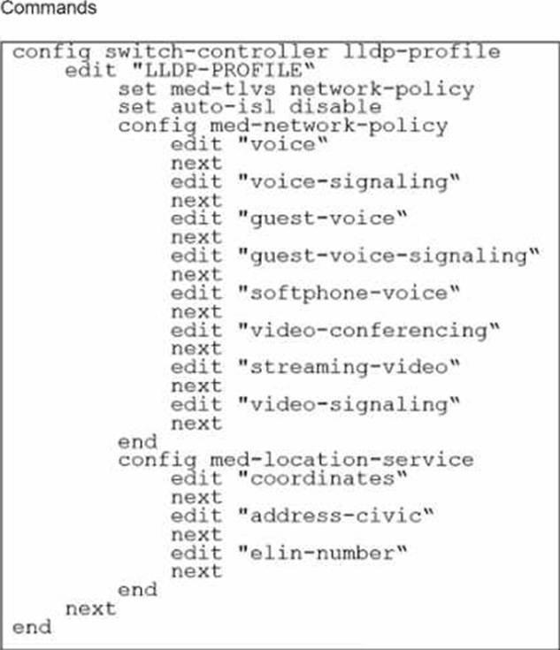
The profile shown in the exhibit is assigned to a group of managed FortiSwitch ports, and these ports are connected to endpoints which are powered by PoE.
Which configuration action can you perform on the LLDP profile to cause these endpoints to exchange PoE information and negotiate power with the managed FortiSwitch?
- A . Create new a LLDP-MED application type to define the PoE parameters.
- B . Assign a new LLDP profile to handle different LLDP-MED TLVs.
- C . Define an LLDP-MED location ID to use standard protocols for power.
- D . Add power management as part of LLDP-MED TLVs to advertise.
D
Explanation:
To cause endpoints to exchange PoE information and negotiate power with the managed FortiSwitch via LLDP, you should configure the LLDP profile to include power management in the advertised LLDP-MED TLVs. Here are the steps:
Access the LLDP Profile Configuration: Start by entering the LLDP profile configuration mode with the command:
config switch-controller lldp-profile
edit "LLDP-PROFILE"
Enable MED-TLVs: Ensure that MED-TLVs (Media Endpoint Discovery TLVs) are enabled. These TLVs are used for extended discovery relating to network policies, including PoE, and are essential for PoE negotiation. They include power management which is crucial for the negotiation of PoE parameters between devices. The command to ensure network policies are set might look like:
set med-tlvs network-policy
Add Power Management TLV: Specifically add or ensure the power management TLV is part of the configuration. This will advertise the PoE capabilities and requirements, enabling dynamic power allocation between the FortiSwitch and the connected devices (like VoIP phones or wireless access points ).
This can typically be done within the network-policy settings:
config med-network-policy
edit <policy_index>
set poe-capability
next
end
Save and Apply Changes: Exit the configuration blocks properly ensuring changes are saved:
End
Verify Configuration: It’s always good practice to verify that your configurations have been applied correctly. Use the appropriateshoworgetcommands to review the LLDP profile settings.
By adding the power management as part of LLDP-MED TLVs, the FortiSwitch will be able to communicate its power requirements and capabilities to the endpoints, thereby facilitating a dynamic power negotiation that is crucial for efficient PoE utilization.
Reference: For more detailed information and additional configurations, you can refer to the FortiSwitch Managed Switches documentation available on Fortinet’s official documentation site: Fortinet Product Documentation
Your team is deploying a single FortiGate and a single FortiSwitch across 100 branch offices. The goal is to expedite deployment while avoiding manual configuration errors.
Which method would allow you to achieve this goal most efficiently? (Choose one answer)
- A . Push FortiGate and FortiSwitch configurations through FortiEdge Cloud.
- B . Use the cloud Model-as-a-Service (MaaS) to push the configuration of both FortiGate and FortiSwitch.
- C . Use zero-touch provisioning (ZTP) through FortiManager.
- D . Ensure that devices engage FortiSwitch Manager to retrieve their configurations.
C
Explanation:
According to theFortiOS 7.6 Administration Guideand theFortiManager 7.6 Study Guide, the most efficient and scalable method for deploying standardized configurations across a high volume of sites (such as 100 branch offices) isZero-Touch Provisioning (ZTP) through FortiManager.
ZTP allows administrators to createModel DevicesandProvisioning Templateswithin FortiManager before the physical hardware is even unboxed. When a factory-reset FortiGate at a branch office is connected to the internet, it automatically reaches out toFortiCloud (FortiDeploy) to discover its assigned management entity. Once redirected to the centralFortiManager, the FortiGate retrieves its full configuration, including theFortiLinksettings required to manage the local FortiSwitch.
The 7.6 documentation highlights that because the FortiSwitch is managed via FortiLink, its configuration is technically part of the FortiGate’s managed objects. Therefore, by using FortiManager to push a single template that includes both the FortiGate settings and theSwitch Controllerconfigurations, the team can ensure that every branch office is configured identically and without manual CLI intervention. This method significantly reduces the risk of human error and ensures rapid, consistent deployment across the entire fabric. Options A and B refer to cloud management platforms that are effective but do not offer the same level of integrated, template-driven orchestration for large-scale enterprise ZTP as FortiManager.
Option D is incorrect as "FortiSwitch Manager" is not the primary orchestration tool for branch-wide ZTP in a FortiLink-integrated environment.
Exhibit.
port24 is the only uplink port connected to the network where access to FortiSwitch management services is possible. However, FortiSwitch is still not accessible on the management interface.
Which two actions should you take to fix the issue and access FortiSwitch? (Choose two.)
- A . You must add port24 native VLAN as an allowed VLAN on internal.
- B . You must add VLAN ID 200 to the allowed VLANS on internal.
- C . You must allow VLAN ID 4094 on port24, if management traffic is tagged.
- D . You should use VLAN ID 4094 as the native VLAN on port24.
A, C
Explanation:
To enable access to the FortiSwitch management interface from the network, certain configuration adjustments need to be made, particularly considering the VLAN settings displayed in the exhibit:
Adding port24 native VLAN to the allowed VLANs on internal (Option A): The management VLAN (VLAN 4094 in this case, as it is set as the native VLAN on the ‘internal’ interface of the FortiSwitch) must be included in the allowed VLANs on the interface that provides management connectivity. Since port24 is set with a different native VLAN (VLAN 100), VLAN 4094 (the management VLAN) should be allowed through to ensure connectivity.
Allow VLAN ID 4094 on port24 if management traffic is tagged (Option C): Management traffic is tagged on VLAN 4094. Since port24 is connected to the network and serves as an uplink, allowing VLAN 4094 ensures that management traffic can reach the management interface of the FortiSwitch through this port.
The changes align with Fortinet’s best practices for setting up management VLANs and ensuring they are permitted on the relevant switch ports for proper management traffic flow.
Reference: FortiGate Infrastructure and Security 7.6 Study Guides
Best practices for VLAN configurations in Fortinet’s technical documentation
Refer to the exhibits.
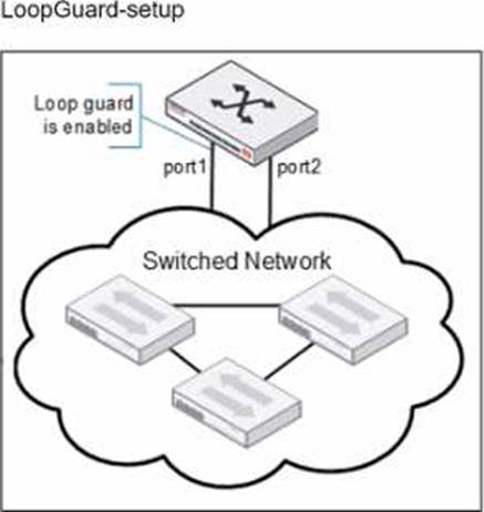
Port1 and port2 are the only ports configured with the same native VLAN 10.
What are two reasons that can trigger port1 to shut down? (Choose two.)
- A . port1 was shut down by loop guard protection.
- B . STP triggered a loop and applied loop guard protection on port1.
- C . An endpoint sent a BPDU on port1 that it received from another interface.
- D . Loop guard frame sourced from port 1 was received on port 1.
A, B
Explanation:
When loop guard is enabled on port1 and port2 configured with the same native VLAN (VLAN 10), there are specific scenarios under which port1 can be shut down due to loop guard operation:
When Dynamic Host Configuration Protocol (DHCP) snooping is enabled on a FortiSwitch VLAN, which two statements are true? (Choose two answers)
- A . DHCP replies are accepted only on trusted ports.
- B . DHCP snooping blocks all unicast traffic.
- C . Option 82 can be inserted into DHCP requests.
- D . DHCP requests are dropped if sent from trusted ports.
A, C
Explanation:
According to theFortiSwitchOS 7.6 Administration Guideand theFortiLink 7.6 Study Guide, DHCP snooping is a security feature that prevents rogue DHCP servers from distributing incorrect IP addresses on a network. Once enabled for a specific VLAN, the switch differentiates between trustedanduntrustedports to regulate DHCP traffic.
Trusted Ports and DHCP Replies (Option A): In a managed FortiSwitch environment, all ports areuntrusted by default. To allow a DHCP server (such as a FortiGate or an external server) to provide IP addresses, the administrator must explicitly set the connecting port astrusted. DHCP snooping validates incoming packets; it allowsDHCP server messages (such as DHCPOFFER and DHCPACK) only on these trusted ports. Any DHCP server reply arriving on an untrusted port is identified as coming from a potentially rogue source and is discarded by the switch.
Option 82 Data Insertion (Option C): FortiSwitch supportsDHCP Option 82 (also known as the Relay Information Option), which provides additional security by appending location-specific information (such as the Circuit ID and Remote ID) toDHCP request packets. When DHCP snooping is active, the switch can be configured to insert this data into client requests as they enter untrusted ports. This allows the upstream DHCP server to identify the specific physical port or VLAN from which the request originated, even if the server is located in a different subnet.
Regarding the incorrect options:
Option B is false as DHCP snooping only inspects and filters DHCP-specific traffic, not general unicast data.
Option D is incorrect because DHCP requests (client-to-server) are generally permitted on all ports to ensure clients can find a server, though some configurations allow dropping requests from untrusted sources if they do not meet specific security criteria.
Which two types of Layer 3 interfaces can participate in dynamic routing on FortiSwitch? (Choose two.)
- A . Detected management interfaces
- B . Loopback interfaces
- C . Switch virtual interfaces
- D . Physical interfaces
B, C
Explanation:
In dynamic routing on FortiSwitch, certain types of interfaces are utilized to participate in the routing processes. The types of interfaces that can be used include:
Loopback Interfaces (B): Loopback interfaces are virtual interfaces that are always up, making them ideal for use in routing protocols where a stable interface is necessary. They are commonly used to establish router IDs and manage routing information more reliably.
Switch Virtual Interfaces (C): Switch Virtual Interfaces (SVIs) are assigned to VLANs and can have IP
addresses assigned to them, making them capable of participating in Layer 3 routing. SVIs are essential for routing between different VLANs on a switch and can participate in dynamic routing protocols to advertise networks or make routing decisions.
Physical Interfaces (D) andDetected Management Interfaces (A) are not typically used directly by dynamic routing protocols for their operations in the context of FortiSwitch.
Reference: For more information on how these interfaces interact with dynamic routing protocols, you can check the FortiSwitch documentation on Fortinet’s official documentation site: Fortinet Product Documentation
Refer to the exhibit.
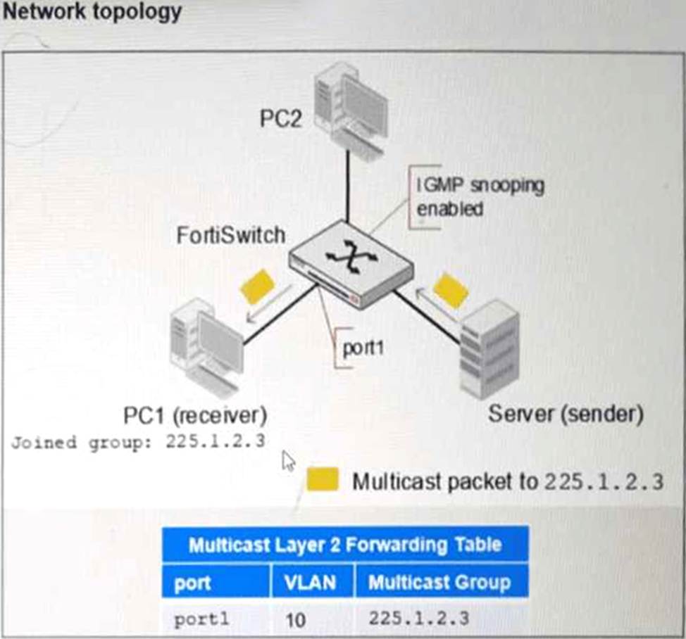
PC1 connected to port1 has joined multicast group 225.1.2.3 on VLAN 10 with IGMP snooping enabled.
What will happen if you disable IGMP snooping on FortiSwitch? (Choose one answer)
- A . PC1 will be removed from the multicast group 225.1.2.3.
- B . The FortiSwitch will stop processing IGMP report join messages.
- C . Multicast traffic for 225.1.2.3 will be flooded to all ports.
- D . Multicast traffic will stop until a multicast receiver is detected.
C
Explanation:
According to theFortiSwitchOS 7.6 Administration Guideand theFortiSwitch 7.6 Study Guide, Internet Group Management Protocol (IGMP) snooping is a Layer 2 mechanism that allows a switch to "listen" to IGMP conversations between hosts and routers to maintain a map of which ports require specific multicast streams. When IGMP snooping is enabled, the switch populates aMulticast Layer 2 Forwarding Table (as shown in the exhibit), which ensures that multicast traffic is only forwarded to ports where a receiver has explicitly requested it (e.g., PC1 on port1 ).
When IGMP snooping is disabled, the switch no longer maintains this granular forwarding table. By default, a Layer 2 switch that is not performing IGMP snooping treats multicast traffic as if it were broadcast traffic. Consequently, instead of being intelligently forwarded only to the interested receiver (PC1), the multicast traffic for group 225.1.2.3 will be flooded to all ports within the same VLAN (VLAN 10). This means PC2, even if it has not joined the group, will receive the multicast packets at the physical layer, leading to unnecessary bandwidth consumption and increased CPU load on unintended recipients.
The documentation explicitly states that disabling IGMP snooping reverts the switch to a "flood-all" behavior for multicast frames within the broadcast domain.
Option A is incorrect because the host (PC1) remains a member of the group; only the switch’s forwarding logic changes.
Option B is incorrect as the switch may still see the messages but will not act on them to prune ports.
Option D is incorrect as disabling the feature removes the prune/stop mechanism, causing traffic to flow everywhere rather than stopping.