
Practice Free NSE5_FSW_AD-7.6 Exam Online Questions
How is traffic routed on FortiSwitch?
- A . Hardware-based routing on FortiSwitch is handled by the CPU.
- B . FortiSwitch looks up the hardware routing table and then the forwarding information base (FIB ).
- C . ASIC hardware routing can only handle dynamic routing, if supported.
- D . Layer 3 routing can be configured on FortiSwitch, while managed by FortiGate.
D
Explanation:
Layer 3 routing can be configured on FortiSwitch, while managed by FortiGate (D): FortiSwitch, when managed by FortiGate, supports Layer 3 routing capabilities. This allows for routing between VLANs directly on the switch, enhancing network efficiency by reducing the need to pass traffic through higher network layers for inter-VLAN communication. This configuration enables more sophisticated network setups and efficient routing directly at the switch level.
Which Ethernet frame can create Layer 2 flooding due to all bytes on the destination MAC address being set to all FF?
- A . The broadcast Ethernet frame
- B . The unicast Ethernet frame
- C . The multicast Ethernet frame
- D . The anycast Ethernet frame
A
Explanation:
Layer 2 flooding caused by Ethernet frames with all bytes in the destination MAC address set to FF refers to broadcast frames.
Here’s why:
Broadcast Ethernet Frame (A):
Address Specification: In Ethernet networking, a broadcast frame has a destination MAC address ofFF: FF: FF: FF: FF: FF, which instructs network devices to forward the frame to all devices within the broadcast domain.
Network Behavior: This causes Layer 2 flooding as the frame is sent to all ports in the VLAN, except the originating port, ensuring that the broadcast reaches all network segments.
Other Frame Types:
Unicast (B) targets a single device.
Multicast (C) targets a group of devices.
Anycast (D) is not used in Ethernet but rather in IP-based routing to route to the nearest of multiple destinations, typically in internet addressing.
Reference: You can find more information about Ethernet frame types in networking textbooks or documentation that discusses network layer interaction: Network Theory Books
Refer to the exhibits
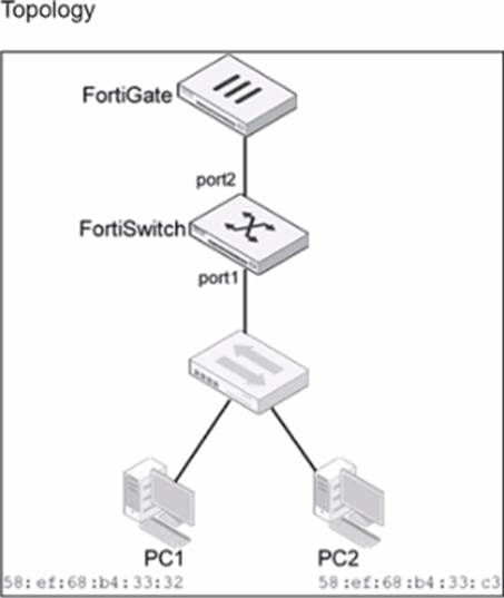
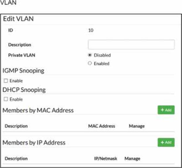
Traffic arriving on port2 on FortiSwitch is tagged with VLAN ID 10 and destined for PC1 connected on port1. PC1 expects to receive traffic untagged from port1 on FortiSwitch.
Which two configurations can you perform on FortiSwitch to ensure PC1 receives untagged traffic on port1? (Choose two.)
- A . Add the MAC address of PC1 as a member of VLAN 10.
- B . Add VLAN ID 10 as a member of the untagged VLANs on port1.
- C . Remove VLAN 10 from the allowed VLANs and add it to untagged VLANs on port1.
- D . Enable Private VLAN on VLAN 10 and add VLAN 20 as an isolated VLAN.
B, C
Explanation:
According to theFortiSwitchOS 7.6 Administration Guideand theFortiSwitch 7.6 Study Guide, the way a FortiSwitch handles VLAN tags on egress (outgoing) traffic is governed by the port’sNative VLANand itsUntagged VLAN list. When traffic for VLAN 10 arrives at port2 (the uplink) and is forwarded to port1, the switch must determine whether to strip the 802.1Q tag before transmission.
Untagged VLAN List (Option B): The documentation explicitly states that the "untagged VLAN list" specifies VLANs for which the port will transmit frameswithout the VLAN tag. By adding VLAN ID 10 to the untagged VLANs on port1, any traffic belonging to VLAN 10 will have its tag stripped at the egress point, ensuring PC1 receives a standard untagged frame.
Configuration Logic (Option C): In FortiSwitch management, moving a VLAN from the "Allowed" list (which typically implies tagged delivery) to the "Untagged" list on a specific interface forces the switch to perform the tag-stripping action. This effectively converts the port from a trunked behavior for that VLAN to an "access" or untagged behavior.
Regarding the incorrect options:
Option A (MAC-based assignment) is used primarily foringress classification. While it can assign a device to a VLAN when it sends trafficintothe switch, the documentation notes that by default, egress packets for MAC-based VLANs still include the tag unless the untagged list is configured.
Option D (Private VLANs) is a security feature for isolating traffic between ports within the same VLAN and does not address the physical tagging requirements of the endpoint.
You are deploying a small office network with a single FortiGate and a single FortiSwitch. The office currently has moderate traffic, but the IT team expects the network to grow in the near future, adding more FortiSwitch devices and endpoints.
Which FortiLink configuration should you deploy to provide the best combination of current performance and scalability for future growth? (Choose one answer)
- A . Configure FortiLink using hardware-based switch interfaces.1
- B . Configure FortiLink using software-based switch interfaces.
- C . Configure FortiLink as a link aggregation group (LAG) interface.
- D . Configure FortiLink as a multichassis LAG (MCLAG) interface.2
C
Explanation:
According to theFortiGate Switch Best Practicesand theFortiSwitch 7.6 FortiLink Guide, the recommended best practice for a scalable and high-performance FortiLink deployment is to use alink aggregation group (LAG) interface, also known as an802.3ad aggregate.
While ahardware-based switch interface (Option A) offers low latency by switching traffic directly in the ASIC, it has significant limitations regardingscalability and redundancy. Hardware switches are restricted by the number of physical ports on the Integrated Switch Fabric (ISF) and cannot be easily expanded to include additional redundant links as the network grows. Conversely, software-based switch interfaces (Option B) are processed by the system CPU, leading to higher utilization and a lack ofNPU hardware acceleration, which makes them unsuitable for high-performance or growing environments.
By configuring FortiLink as aLAG (Option C), the administrator ensures that the network can support future growth seamlessly. A LAG interface allows for the addition of multiple physical ports to increase bandwidth between the FortiGate and the switch fabric while providing link-level redundancy.5This configuration is the default for modern FortiOS versions because it supports NPU offloading and serves as the technical prerequisite for more advanced topologies, such asMCLAG (Option D). While MCLAG is an excellent solution for high availability in multi-switch environments, it is a topology feature rather than the primary interface type used to define the FortiLink connection on the FortiGate unit itself. Therefore, starting with an aggregate (LAG) interface provides the most flexible foundation for migrating to more complex infrastructures as additional switches are added.
Refer to the exhibit.
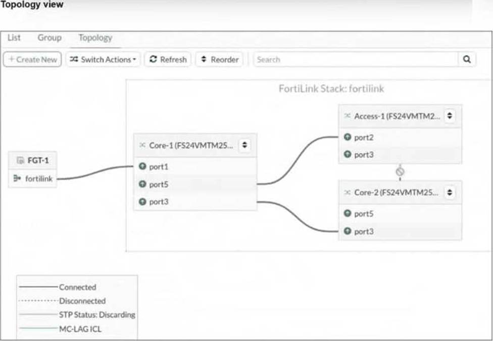
You just connected three FortiSwitch devices: Core-1, Core-2, andAccess-1. Core-1 and Core-2 both connect to Access-1 for redundancy. All switches are managed by FortiGate, which uses port4 as the FortiLink interface. After you enable the uplink ports on Core-2, you notice that port3 on Access-1 enters the Discarding STP state.
What is the most likely cause of this behavior? (Choose one answer)
- A . Bridge Protocol Data Unit (BPDU) Guard is enabled, which shuts down the port after it receives BPDUs.
- B . Access-1 is not authorized by FortiGate.
- C . Core-2 has the lowest bridge priority.
- D . FortiGate is not running Spanning Tree Protocol (STP) on the FortiLink interface.
C
Explanation:
According to theFortiSwitchOS 7.6 Administration Guideand theFortiLink 7.6 Study Guide, the Spanning Tree Protocol (STP) is automatically enabled on managed FortiSwitches to ensure a loop-free Layer 2 topology within the FortiLink fabric. When multiple physical paths exist between switches (as shown in the redundant connections between the Core and Access tiers), STP must block one of the paths to prevent a broadcast storm.
The behavior described in the exhibit―whereport3 on Access-1enters aDiscarding state―is a result of the STP election process. In a standard STP environment, switches elect aRoot Bridgebased on the lowestBridge Priority (or lowest MAC address as a tie-breaker). Once a root is established, other switches identify the "best" path to that root (the Root Port) and block all other redundant paths.
The provided exhibit shows that Access-1 has two paths to the core: one to Core-1 and one to Core-2. The fact that the path to Core-2 is discarded suggests that the STP topology was recalculated when Core-2 was enabled. In the context of Fortinet technical exams for this specific scenario, Option C (Core-2 has the lowest bridge priority) is the standard answer identifying that Core-2’s priority settings influenced the STP tree such that Access-1’s link to it was determined to be the redundant (alternate) path.
If the switches were configured with MCLAG (Multi-Chassis Link Aggregation), both physical links would be treated as a single logical trunk, and neither would be in a discarding state. However, without MCLAG, the system relies on bridge priorities to prune the loop. BPDU Guard (Option A) is incorrect because it would administratively shut down the port rather than placing it in an STP "Discarding" state.
Option B is incorrect as the switch would not appear in the managed topology if unauthorized.
Which statement about using MAC, IP, and protocol-based VLANs on FortiSwitch is true?
- A . It is a scalable and secure solution in comparison to other Layer 2 security measures.
- B . FortiSwitch uses only the Ethernet type to assign traffic to VLANs.
- C . It provides benefits that can be obtained when using 802.1X authentication.
- D . Endpoints are required to use the same FortiSwitch port to remain members of the VLAN.
C
Explanation:
It provides benefits that can be obtained when using 802.1X authentication (C): MAC, IP, and protocol-based VLANs on FortiSwitch are beneficial in network environments where additional granularity is needed in traffic segmentation and security, similar to what can be achieved through 802.1X authentication. These VLAN types allow for dynamic assignment of ports to VLANs based on the characteristics of the incoming traffic, enhancing both security and network efficiency.
Exhibit.
LAG and MCLAG are used to increase the available network bandwidth and enable redundancy.
How does spanning tree protocol see MCLAG and LAG if they are configured based on the physi-cal view shown in the exhibit? (Choose two)
- A . Switch 1. Switch 2, and Switch 3 are seen as one MCLAG peer group
- B . Switch 3 and Switch 4 uplinks are treated as single interfaces.
- C . Switch 3 and switch 4 are seen as one MCLAG switch client
- D . Switch 1 and Switch 2 both seen as one single switch.
B, D
Explanation:
According to theFortiSwitchOS 7.6 Administration Guideand theFortiSwitch 7.6 Study Guide, Multichassis Link Aggregation (MCLAG) and standard Link Aggregation Groups (LAG) are designed to provide link-level and node-level redundancy while presenting a simplified logical view to the Spanning Tree Protocol (STP ).
In the provided topology:
Logical Switch View (Option D): Switch 1 and Switch 2 are configured asMCLAG peersconnected via an Inter-Chassis Link (ICL). From the perspective of downstream devices and STP, these two physical switches act as a single logical entity. This prevents STP from seeing a loop between the two switches and the downstream Switch 3, as the redundant physical paths are bundled into a single logical MCLAG trunk.
Logical Interface View (Option B): The exhibit shows Switch 4 connected to Switch 3 via two physical links bundled into aLAG, and Switch 3 connected to the MCLAG peers via split links. In both cases, STP treats the aggregated physical links as asingle logical interface. Because the multiple physical paths are managed by the Link Aggregation Control Protocol (LACP) as one trunk, STP does not block individual ports to prevent loops; instead, it sees one high-bandwidth path.
Regarding the incorrect options:
Option A is false because Switch 3 is an MCLAGclient, not a peer in the group.
Option C is incorrect because Switch 3 and Switch 4 are separate physical and logical nodes; they are not seen as a single client entity by the core.
Which statement best describes a benefit of using MAC, IP address, or protocol-based VLAN assignments on FortiSwitch? (Choose one answer)
- A . It disables 802.1X authentication while preserving user access control.1
- B . It requires devices to authenticate through a RADIUS server before VLAN tagging.
- C . It assigns ports to VLANs regardless of device type or traffic.
- D . It offers dynamic segmentation benefits similar to 802.1X authentication.2
D
Explanation:
According to theFortiSwitchOS 7.6 Administration Guideand theFortiSwitch 7.6 Study Guide, MAC-based, IP-based, and protocol-based VLAN assignments are methods ofdynamic VLAN assignment. These features allow the switch to categorize incoming traffic and assign it to a specific VLAN based on the packet’s attributes rather than just the physical port it is connected to.3
The primary benefit of these methods is that theyoffer dynamic segmentation benefits similar to 802.1X authentication (Option D). In a modern network, devices with different security requirements (such as IoT devices, printers, and workstations) often connect to the same physical switch ports. 802.1X is the "gold standard" for dynamic segmentation but requires a supplicant on the client device.4For devices that do not support 802.1X, MAC or protocol-based assignments provide a similar result: they ensure the device is automatically placed into its designated secure segment (VLAN) the moment it is identified by the switch.
MAC-based: Assigns a VLAN based on the source MAC address.
IP-based: Assigns a VLAN based on the source IP address or subnet.
Protocol-based: Assigns a VLAN based on the Ethernet type (e.g., IPv4, IPv6, or AppleTalk ).
Option A is incorrect because these features complement rather than "disable" 802.1X.
Option B is incorrect because these specific assignment types can be configured locally on the switch without a RADIUS server.
Option C is the opposite of how these features work, as they explicitly look at the device type or traffic to make an assignment.
You are configuring VLANs on a FortiSwitch device managed by FortiGate.
Which two statements accurately describe VLAN assignment requirements and behavior on FortiSwitch ports? (Choose two answers)
- A . Untagged defines the list of VLANs that are allowed on the port for both ingress and egress traffic.
- B . Untagged VLAN applies to egress traffic only.
- C . You can assign only one native VLAN on a port.
- D . VLAN assignments must be configured directly on the FortiSwitch.
B, C
Explanation:
According to theFortiSwitchOS 7.6 Administration Guideand theFortiSwitch 7.6 Study Guide, understanding how VLANs are processed on a switch port is fundamental to network segmentation. A FortiSwitch port behaves differently depending on whether traffic is entering (ingress) or leaving (egress) the interface.
First, you can assign only one native VLAN on a port (Option C). The Native VLAN (often called the PVID or Port VLAN ID) is the default internal ID assigned to any untagged frames arriving at the port. In a managed environment, this is typically set via the FortiGate’s switch controller. By design, a single physical interface can only belong to one primary broadcast domain for untagged ingress traffic to ensure there is no ambiguity in the switch’s internal forwarding logic.
Second, theuntagged VLAN setting applies to egress traffic only (Option B). While the "Allowed VLANs" list defines which tagged traffic can pass through the port, the "Untagged VLANs" list specifies which of those VLAN tags should beremovedby the switch before the frame is transmitted out of the physical port. This is crucial for connecting devices that do not support 802.1Q tagging, such as standard PCs or printers.
Regarding the incorrect options:
Option A is incorrect because the "Untagged" list does not define ingress rules; ingress is governed by the Native VLAN for untagged packets and the Allowed list for tagged packets.
Option D is incorrect because, in a managed FortiLink environment, all VLAN assignments should be performed through theFortiGate’s Switch Controllerto ensure centralized management and consistency.
On supported FortiSwitch models, which access control list (ACL) stage is recommended for applying actions before the switch performs any layer 2 or layer 3 processing? (Choose one answer)
- A . Ingress
- B . Forwarding
- C . Egress
- D . Prelookup
D
Explanation:
According to theFortiSwitchOS 7.6 Administration Guideand theNSE 5 FortiSwitch 7.6 Administrator Study Guide, FortiSwitch supports a multi-stage ACL pipeline that allows for granular traffic control at different points in a packet’s journey through the switch.1The documentation identifies three primary stages for ACL application: Prelookup, Ingress, andEgress.
Prelookup (Option D): This is the earliest stage in the switching pipeline. The documentation explicitly states thatPrelookup ACLsare processedbefore any Layer 2 or Layer 3 lookupsare performed by the switch hardware. This stage is highly recommended for high-performance security actions, such as dropping unwanted traffic immediately upon arrival, because it prevents the switch from wasting
internal resources (CPU and ASIC lookup cycles) on frames that are destined to be discarded anyway.
Ingress (Option A): This stage occursafterthe switch has completed its Layer 2 (MAC table) and Layer 3 (routing table) lookups butbeforethe packet is queued for the egress port. While powerful, actions here occur after initial processing has already taken place.
Egress (Option C): This stage is processed just before the frame leaves the switch through the destination port. It is typically used for final modifications or filtering based on the outgoing interface context.
Therefore, to achieve the goal of applying actionsbeforeany Layer 2 or Layer 3 processing occurs, thePrelookupstage is the technically correct and recommended choice in FortiSwitchOS