
Practice Free JN0-664 Exam Online Questions
Exhibit
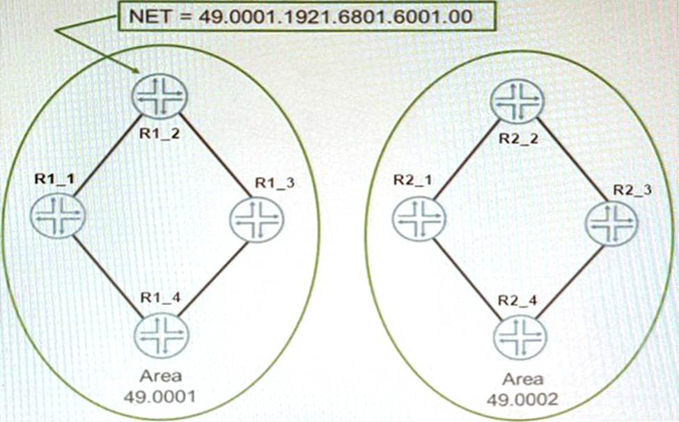
The network shown in the exhibit is based on IS-IS
Which statement is correct in this scenario?
- A . The NSEL byte for Area 0001 is 00.
- B . The area address is two bytes.
- C . The routers are using unnumbered interfaces
- D . The system IDofR1_2 is 192.168.16.1
B
Explanation:
IS-IS is an interior gateway protocol that uses link-state routing to exchange routing information among routers within a single autonomous system. IS-IS uses two types of addresses to identify routers and areas: system ID and area address. The system ID is a unique identifier for each router in an IS-IS domain. The system ID is 6 octets long and can be derived from the MAC address or manually configured. The area address is a variable-length identifier for each area in an IS-IS domain. The area address can be 1 to 13 octets long and is composed of high-order octets of the address. An IS-IS instance may be assigned multiple area addresses, which are considered synonymous. Multiple synonymous area addresses are useful when merging or splitting areas in the domain1. In this question, we have a network based on IS-IS with four routers (R1_1, R1_2, R2_1, and R2_2) belonging to area 0001. The area address for area 0001 is 49.0001. The NSEL byte for area 0001 is the last octet of the address, which is 01. The NSEL byte stands for Network Service Access Point Selector (NSAP Selector) and indicates the type of service requested from the network layer2. Therefore, the correct statement in this scenario is that the NSEL byte for area 0001 is 01.
References:
1: https://www.cisco.com/c/en/us/td/docs/ios-xml/ios/iproute_isis/configuration/xe-16/irs-xe-16-book/irs-ovrvw-cf.html
2: https://www.juniper.net/documentation/us/en/software/junos/is-is/topics/concept/is-is-routing-overview.html
Exhibit
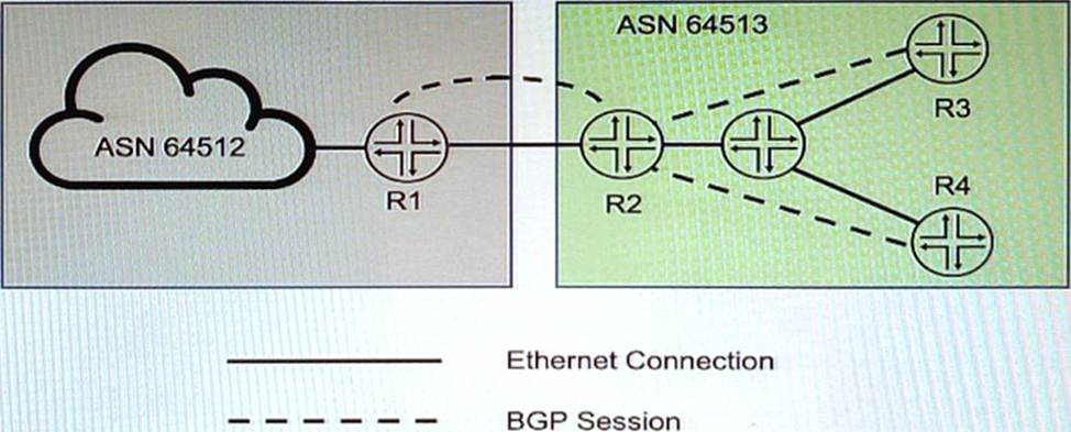
You want to implement the BGP Generalized TTL Security Mechanism (GTSM) on the network
Which three statements are correct in this scenario? (Choose three)
- A . You can implement BGP GTSM between R2, R3, and R4
- B . BGP GTSM requires a firewall filter to discard packets with incorrect TTL.
- C . You can implement BGP GTSM between R2 and R1.
- D . BGP GTSM requires a TTL of 1 to be configured between neighbors.
- E . BGP GTSM requires a TTL of 255 to be configured between neighbors.
AEC
Explanation:
You can implement BGP GTSM between R2, R3, and R4 – GTSM can typically be implemented on any BGP peering relationship to protect against certain types of attacks, assuming that the routers are directly connected or that there’s a controlled number of hops in between them.
BGP GTSM requires a firewall filter to discard packets with incorrect TTL – While GTSM itself checks the TTL of received BGP packets and drops those that don’t meet the expected TTL value, configuring a firewall filter can provide an additional layer of security to enforce this policy on the routers.
BGP GTSM requires a TTL of 255 to be configured between neighbors – The principle behind GTSM is that BGP packets sent between directly connected peers should have their TTL set to 255. When a BGP message is received, the TTL is checked, and if it is not within the expected range (usually close to 255), the packet is considered invalid.
Refer to the Exhibit:
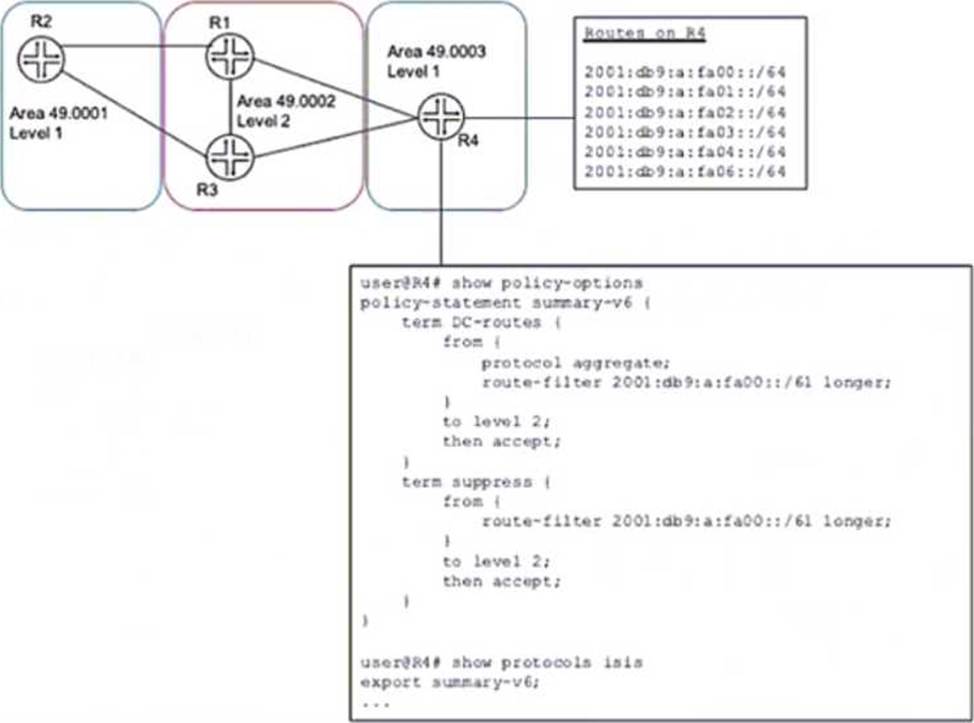
A network designer would like to advertise a single summary route from R4 to IS-IS level 2 neighbors as shown in the exhibit, but the configuration is not working.
Which three configuration changes will accomplish this task? (Choose three.)
- A . delete protocols isis export summary-v6
- B . set protocols isis import summary-v6
- C . delete policy-options policy-statement summary-v6 term DC-routes from route-filter 2001:db5:a:fa00::/61 longer
- D . set policy-options policy-statement summary-v6 term DC-routes from route-filter 2001:dbS:a:fa00::/6l exact
- E . set policy-options policy-statement summary-v6 term suppress then reject
Exhibit
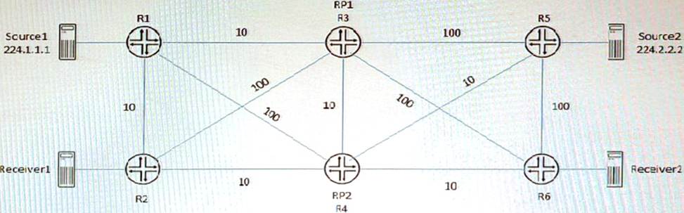
Referring to the exhibit, PIM-SM is configured on all routers, and Anycast-RP with Anycast-PIM is used for the discovery mechanism on RP1 and RP2. The interface metric values are shown for the OSPF area.
In this scenario, which two statements are correct about which RP is used? (Choose two.)
- A . Source2 will use RP2 and Received will use RP2 for group 224.2.2.2.
- B . Source2 will use RP1 and Receiver2 will use RP1 for group 224.2.2.2.
- C . Source1 will use RP1 and Receiver1 will use RP1 for group 224.1.1.1.
- D . Source1 will use RP1 and Receiver1 will use RP2 for group 224.1 1 1
A,C
Explanation:
A sham link is a logical link between two PE routers that belong to the same OSPF area but are connected through an L3VPN. A sham link makes the PE routers appear as if they are directly connected, and prevents OSPF from preferring an intra-area back door link over the VPN backbone. A sham link creates an OSPF multihop neighborship between the PE routers using TCP port 646. The PEs exchange Type 1 OSPF LSAs instead of Type 3 OSPF LSAs for the L3VPN routes, which allows OSPF to use the correct metric for route selection1.
Exhibit
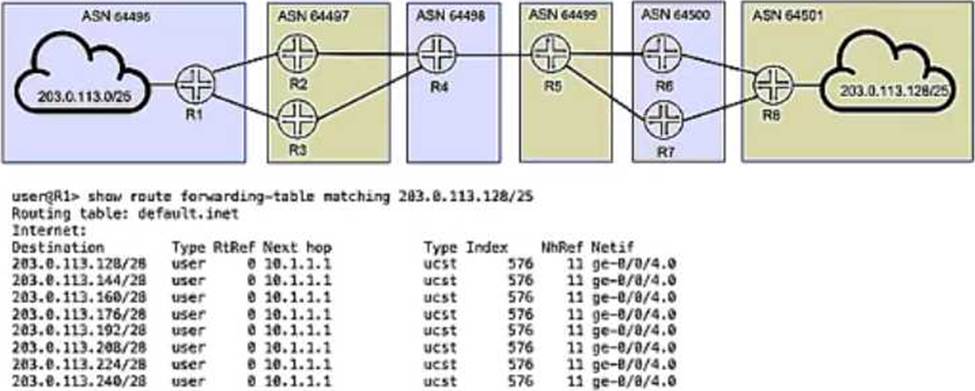
You are troubleshooting the connection between AS 64496 and AS 64497 and notice that only one of the paths is being used for traffic forwarding.
Referring to the exhibit, which three actions will ensure that R1 is configured properly for load balancing BGP routes? (Choose three.)
- A . Verify that the routing table on R1 has BGP routes for 203.0.113.128/25 with multiple next hops.
- B . Verify that the multipath option is configured under protocols bgp on both R2 and R3.
- C . Verify that there is a load balancing export policy under routing-options for the received BGP routes on R1.
- D . Verify that the multipath option is configured under protocols bgp on R1.
- E . Verify that an import load balancing policy exists under protocols bgp for the received BGP routes on R1.
ACD
Explanation:
To ensure R1 is properly configured for load balancing BGP routes, the three actions required are A (verify the routing table on R1 has BGP routes for 203.0.113.128/25 with multiple next hops), D (verify the multipath option is configured under protocols bgp on R1), and E (verify that there is an import load balancing policy under protocols bgp for the received BGP routes on R1). These steps help to ensure that R1 can perform load balancing across multiple available paths.
Refer to the exhibit.
Click the Exhibit button.
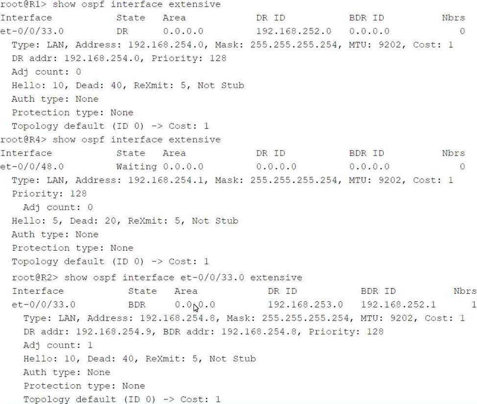
You have an OSPF environment. You have recently added a router called R4 that is directly connected to R1 and R2. You discover that R4 is only peering with R2.
Referring to the exhibit, how would you correct the peering?
- A . Adjust the Priority on R1 to be lower than the Priority on R4.
- B . Change the MTU size on R1 and R2 to be 22 bytes higher than R4’s MTU size.
- C . Adjust the Dead Interval on R4 to match the Dead Interval on R1 and R2.
- D . Adjust the Hello Interval on R1 and R2 to match the Hello Interval on R4.
D
Explanation:
In OSPF, routers form adjacencies by exchanging Hello packets. These packets contain several parameters that must match between OSPF neighbors to establish a successful adjacency. Key among these parameters are the Hello Interval and the Dead Interval.
Let’s analyze the exhibit and the question to determine the correct course of action to ensure that R4 peers with both R1 and R2.
Which two statements are correct about the customer interface in an LDP-signaled pseudo wire? (Choose two)
- A . When the encapsulation is vlan-ccc or extended-vlan-ccc, the configured VLAN tag is not included in the control plane LDP advertisement
- B . When the encapsulation is ethernet-ccc, only frames without a VLAN tag are accepted in the data plane
- C . When the encapsulation is vLan-ccc or extended-vlan-ccc, the configured VLAN tag is included in the control plane LDP advertisement
- D . When the encapsulation is ethemet-ccc, tagged and untagged frames are both accepted in the data plane.
AD
Explanation:
The customer interface in an LDP-signaled pseudowire is the interface on the PE router that connects to the CE device. An LDP-signaled pseudowire is a type of Layer 2 circuit that uses LDP to establish a point-to-point connection between two PE routers over an MPLS network. The customer interface can have different encapsulation types depending on the type of traffic that is carried over the pseudowire. The encapsulation types are ethernet-ccc, vlan-ccc, extended-vlan-ccc, atm-ccc, frame-relay-ccc, ppp-ccc, cisco-hdlc-ccc, and tcc-ccc. Depending on the encapsulation type, the customer interface can accept or reject tagged or untagged frames in the data plane, and include or exclude VLAN tags in the control plane LDP advertisement. The following table summarizes the behavior of different encapsulation types: