
Practice Free JN0-481 Exam Online Questions
You want to route between tenants in a multitenant environment in Juniper Apstra.
What are two ways to accomplish this task? (Choose two.)
- A . Route between VRFs on a VTEP-enabled device.
- B . Use an external device to route between tenants.
- C . Use iBGP to route within the same AS number.
- D . Use virtual networks to route between VRFs.
A, B
Explanation:
In Apstra 5.1 multitenancy, tenants are modeled as routing zones, and each routing zone maps to a distinct VRF to provide strict Layer 3 isolation. Because each tenant’s VRF is separate, “routing between tenants” is effectively inter-VRF routing. Apstra’s routing-zone behavior emphasizes that inter-tenant routing is achieved via external systems: you connect each tenant/routing zone to an external router or firewall (often attached to border leafs), and that external device performs the policy-controlled inter-VRF routing between tenants. This approach is the most common because it centralizes security and compliance controls (stateful inspection, zone policies, NAT, logging) on the firewall/router while keeping the fabric clean and consistent.
A second method is to perform inter-VRF routing on a VTEP-capable border leaf that terminates the tenant VRFs. In EVPN-VXLAN designs, border leafs are frequently the demarcation where tenant VRFs connect to outside domains; when the same border leaf hosts multiple tenant VRFs and is designed to provide L3 services for them, it can act as the routing point between VRFs (subject to your design and security requirements). Junos v24.4 supports VRFs and policy constructs required for controlled route exchange and forwarding behavior, but Apstra’s intent model still expects routing-zone isolation by default―so any inter-tenant connectivity should be explicitly designed and governed, typically at the border.
The same connectivity template is applied to the ge-0/0/6 interface on both borderleaf1 and borderleaf2 nodes. This connectivity template describes the intended configuration of the eBGP session between each of the borderleaf nodes and the external router.
You want to ensure that the 172.23.x/24 routes are not installed in the borderleaf nodes’ Finance routing table.
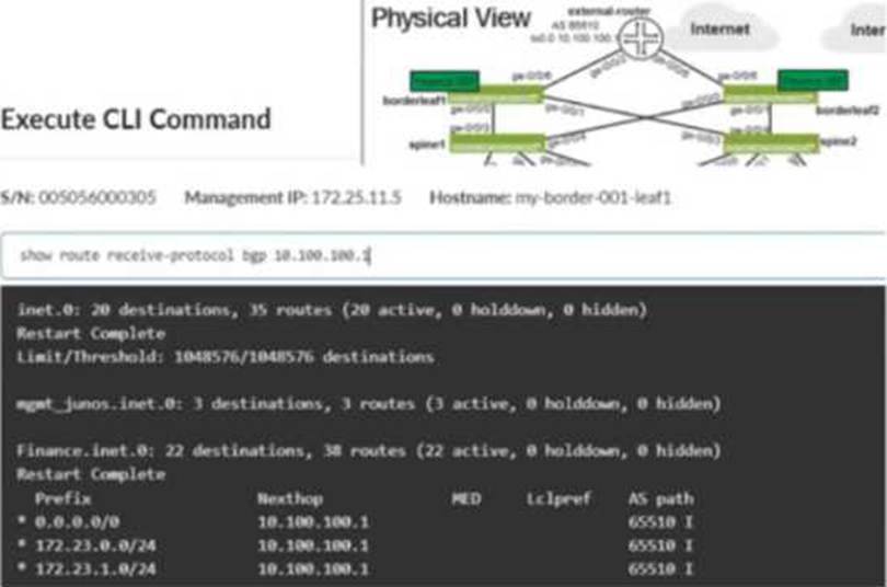
Referring to the exhibit, what would you change in Juniper Apstra to accomplish this task?
- A . Add an aggregate prefix to the routing policy.
- B . Modify the import policy to only allow the default route.
- C . Select the “Expect Default IPv4 Route” checkbox.
- D . Modify the export policy to only allow the default route.
B
Explanation:
The exhibit shows the border leaf receiving multiple routes via BGP from the external router, including 172.23.x/24 prefixes, and those routes appearing in the Finance VRF routing table. To stop these routes from being installed in the Finance table, you must change what the border leaf imports from that eBGP session. In Apstra, this control is implemented through a Routing Policy attached to the protocol session described by the connectivity template. By setting the Import Policy to accept default route only, Apstra renders Junos policy so that only 0.0.0.0/0 is imported into the VRF, while the 172.23.x/24 prefixes are rejected and therefore never installed in Finance.inet.0.
Option C is a common trap: the “Expect Default IPv4 Route” setting is an assurance expectation―it generates an expectation/anomaly if the default route is missing, but it does not change device configuration or filtering behavior. Export-policy changes (option D) would only affect what the border leaf advertises outbound to the external router, not what it learns inbound. Aggregation (option A) does not prevent installation of the specific learned /24s; it changes advertisement behavior rather than import filtering. The correct fix is to tighten the import policy on that external eBGP session.
Verified Juniper sources (URLs):
https://www.juniper.net/documentation/us/en/software/apstra5.1/apstra-user-guide/topics/concept/routing-policies.html
https://www.juniper.net/documentation/us/en/software/apstra6.0/apstra-user-guide/topics/concept/routing-policies.html
https://www.juniper.net/documentation/us/en/software/apstra4.2/apstra-user-guide/topics/concept/connectivity-templates.html
Which type of generic system should you select when adding a new server inside an existing rack type?
- A . Internal generic
- B . Rack generic
- C . External generic
- D . Embedded generic
A
Explanation:
In Apstra 5.1, servers that connect to leaf switches are represented as generic systems so Apstra can model links, apply connectivity templates, attach virtual networks, and validate intent. The selection of generic system type depends on whether the endpoint is considered part of the rack’s internal topology or an external attachment. When you add a new server inside an existing rack type, that server is treated as a component of the rack topology (that is, it lives “within” the rack alongside leaf switches and any other rack-internal endpoints). Apstra documentation refers to such systems as internal generic systems.
Internal generic systems are not managed like switches (no full device management), but they are first-class topology objects: they occupy ports on leaf switches, can be tagged with roles, and can be associated with link definitions that drive correct interface intent (LAG vs single link, VLAN tagging, and virtual network association). This modeling is essential in EVPN-VXLAN fabrics because correct endpoint attachment on leaf ports determines VLAN/VNI mapping and the resulting Junos v24.4 configuration rendered by Apstra.
External generic systems, by contrast, represent devices outside the rack topology (often used for external routers, firewalls, or other non-rack-contained endpoints). Because the question explicitly places the server inside an existing rack type, the correct choice is Internal generic.
Verified Juniper sources (URLs):
https://www.juniper.net/documentation/us/en/software/apstra5.1/apstra-user-guide/topics/topic-map/internal-generic-system-create.html
You have a virtual network that needs controlled access to other virtual networks in the same routing zone. Using the Juniper Apstra Ul. which feature would be used to accomplish this task?
- A . interface policy
- B . anti-affinity policy
- C . routing policy
- D . security policy
D
Explanation:
A security policy is the feature that would be used to accomplish the task of controlling access to other virtual networks in the same routing zone using the Juniper Apstra UI. A security policy allows you to define rules that specify which traffic is allowed or denied between different virtual networks, IP endpoints, or routing zones. A security policy can be applied to one or more virtual networks in the same routing zone, and it can use various criteria to match the traffic, such as source and destination IP addresses, protocols, ports, or tags. A security policy can also support DHCP relay, which enables the forwarding of DHCP requests from one virtual network to another. The other options are incorrect because:
You have a configuration deviation in the Juniper Apstra dashboard.
What does this anomaly indicate in this scenario?
- A . A device’s configuration has been updated by the server.
- B . A device is ready to be configured by the system.
- C . A device’s configuration has been changed using a method outside of Apstra.
- D . A device cannot support a configuration command sent by the system.
C
Explanation:
A configuration deviation (also called a configuration anomaly) in Apstra indicates that the device’s running configuration differs from Apstra’s intended (golden) configuration for that node. In day-to-day operations, this most commonly occurs when an operator makes a change outside of Apstra’s control, such as entering commands directly on the device CLI (for example, on a Junos v24.4 switch), using another automation system, or applying an out-of-band configuration method.
Apstra continuously compares the device’s operational configuration against what it expects based on blueprint intent. When it detects drift, it raises a deviation anomaly so operators can decide how to restore compliance. Typical remediations are either (1) remove/revert the out-of-band change so the device matches intent again, or (2) explicitly acknowledge the change in Apstra (for example, via an accept/suppress workflow, depending on the exact UI action and version), so the deviation is no longer treated as unexpected.
While it is also possible for a deviation to be triggered by a device not accepting a rendered command (capability mismatch), the question asks what the anomaly indicates in this scenario; the primary meaning of “configuration deviation” is configuration changed outside of Apstra and therefore the network is no longer aligned with the intended state. That corresponds to option C.
What are two types of virtual networks defined inside Juniper Apstra software? (Choose two.)
- A . VLAN
- B . L3 VPN
- C . VXLAN
- D . L2 VPN
A, C
Explanation:
In Apstra 5.1, a Virtual Network (VN) is Apstra’s abstraction for a Layer 2 forwarding domain that groups endpoints into a logical segment across the fabric. Apstra defines virtual networks as being constructed using either VLANs or VXLANs. A VLAN-based VN represents a Layer 2 domain identified by a VLAN ID and is typically used where you want traditional VLAN semantics (often in smaller environments, migration scenarios, or designs where an overlay is not required). A VXLAN-based VN represents the same Layer 2 intent but uses a VXLAN VNI for scalable overlay segmentation, which is the common approach in EVPN-VXLAN data center fabrics.
In an IP fabric architecture, VXLAN provides encapsulation to carry tenant segments over the routed underlay, while EVPN provides the control-plane signaling for MAC/IP reachability. Junos v24.4 leaf devices act as VTEPs, mapping local VLANs/bridge-domains to VNIs and participating in EVPN for advertisement and convergence. Apstra’s VN construct allows you to create the segment once (as VLAN or VXLAN type), then consistently attach it to racks, ports, and endpoints through intent-driven workflows (such as connectivity templates and virtual network assignments).
“L2 VPN” and “L3 VPN” are service provider terms and are not the VN “types” in Apstra’s data center reference design. In Apstra, tenant L3 separation is modeled by routing zones (VRFs), while the VN itself is specifically either VLAN-based or VXLAN-based.
Verified Juniper sources (URLs):
https://www.juniper.net/documentation/us/en/software/apstra5.1/apstra-user-guide/topics/concept/virtual-networks.html
https://www.juniper.net/documentation/us/en/software/apstra5.1/apstra-user-guide/topics/topic-map/virtual-network-create.html
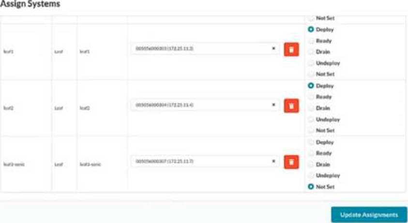
You have created a blueprint and are in the process of assigning systems. You require the leaf3-sonic device in the blueprint but do not want it to actively participate in the routing of the IP fabric.
In the Juniper Apstra UI, which two modes satisfy this requirement? (Choose two.)
- A . Drain
- B . Ready
- C . Deploy
- D . Undeploy
B, D
Explanation:
Apstra deploy modes control how far a device progresses in the configuration lifecycle and whether it becomes active in the fabric. If you must keep leaf3-sonic present in the blueprint (modeled, cabled, and available for future use) but you do not want it to participate in IP-fabric routing, you use modes that keep the device not active.
Ready mode assigns the device to the blueprint and applies only “Ready (Discovery 2)” level configuration―hostnames, interface descriptions, and port speed/breakout settings―while explicitly keeping the device out of fabric routing. In this mode, Apstra does not configure routing/BGP or L3 interface addressing for the IP fabric, so the switch is staged and visible for validation (for example, LLDP wiring checks) but does not forward as part of the Clos underlay.
Undeploy mode removes the complete Apstra service configuration from the device. Operationally, this also ensures the device is not active in the fabric. It is commonly used when a device must be retained in the blueprint inventory/topology but should not be participating (for example, temporarily withdrawn, decommission preparation, or held as a spare).
By contrast, Deploy makes the device active (full rendered fabric configuration, including BGP), and Drain is a maintenance state used to gracefully remove traffic from an already-active device rather than a state for keeping it non-participatory from the outset.
Verified Juniper sources (URLs):
https://www.juniper.net/documentation/us/en/software/apstra6.0/apstra-user-guide/topics/topic-map/device-config-lifecycle.html
https://www.juniper.net/documentation/us/en/software/apstra4.2/apstra-user-guide/topics/topic-map/device-config-lifecycle.html
What is the purpose of an EVPN Ethernet segment identifier (ESI)?
- A . To provide a hop count between devices
- B . To identify Layer 2 frame types for filtering purposes
- C . To specify a BGP community
- D . To prevent loops within a LAG connection
D
Explanation:
In EVPN multihoming, the Ethernet Segment Identifier (ESI) is the mandatory identifier used to represent a multihomed Ethernet segment―for example, a server or downstream switch that is dual-homed to two leaf devices using a single logical LAG/port-channel. By assigning the same ESI to the participating leaf-facing interfaces, the fabric recognizes those links as belonging to one Ethernet segment and can apply EVPN multihoming procedures consistently across the pair.
A key outcome of EVPN multihoming is loop prevention for multi-attached Layer 2 domains. EVPN uses the Ethernet segment concept (identified by the ESI) along with Designated Forwarder (DF) election to ensure that only the appropriate device forwards BUM (broadcast, unknown unicast, multicast) traffic toward the multihomed segment, avoiding duplicate forwarding and L2 loops. In addition, ESI-based multihoming supports resilient forwarding behavior during failures (for example, link or node loss) while maintaining correct advertisement and convergence in the EVPN control plane.
Therefore, among the provided options, the purpose that best matches how ESI is used operationally is to prevent loops within a LAG/multihomed connection, which is fundamental to EVPN-VXLAN data center designs on Junos v24.4 leaf devices and is also explicitly supported by Apstra when modeling ESI-based dual-homing.
Verified Juniper sources (URLs):
https://www.juniper.net/documentation/us/en/software/nce/evpn-lag-multihoming-guide/topics/concept/evpn-lag-guide-introduction.html
https://www.juniper.net/documentation/us/en/software/nce/evpn-lag-multihoming-guide/topics/task/evpn-lag-guide-esi-types-lacp.html
https://www.juniper.net/documentation/us/en/software/junos/evpn/topics/topic-map/evpn-mh-df-election.html
You have an EVPN-VXLAN data center IP fabric, with all single-homed hosts/servers.
Which two EVPN route types are present in this scenario? (Choose two.)
- A . Type 3
- B . Type 7
- C . Type 2
- D . Type 4
A, C
Explanation:
In an EVPN-VXLAN fabric where all hosts are single-homed (each endpoint is attached to only one leaf/VTEP), the EVPN control plane still needs to advertise endpoint reachability and enable BUM handling across the overlay. Two EVPN route types are fundamental in this case: Type 2 and Type 3.
EVPN Route Type 2 (MAC/IP Advertisement) is used to advertise learned MAC addresses and, optionally, associated IP addresses for endpoints connected to the local leaf. This enables remote VTEPs to learn where a given host resides (which VTEP to send unicast traffic to) without relying on data-plane flooding for MAC learning. In Junos v24.4 EVPN-VXLAN deployments, Type 2 routes are the core mechanism for distributing endpoint reachability (MAC and MAC+IP bindings) within the EVPN domain.
EVPN Route Type 3 (Inclusive Multicast Ethernet Tag / IMET) is used to establish the flooding scope for BUM traffic in EVPN-VXLAN. In VXLAN fabrics that use ingress replication (common in data centers), Type 3 routes help build the list of remote VTEPs that should receive replicated BUM traffic for a given segment.
By contrast, Type 4 (Ethernet Segment) routes are associated with EVPN multihoming (ESI-based) and DF election; with only single-homed hosts, Type 4 is not required. Type 7 is not part of the baseline single-homed EVPN-VXLAN host advertisement set in this context.
Verified Juniper sources (URLs):
https://www.juniper.net/documentation/us/en/software/junos/evpn/topics/concept/evpn-bgp-multihoming-overview.html
https://www.juniper.net/documentation/us/en/software/junos/evpn/topics/topic-map/assisted-replication-evpn.html
You are assigning managed devices to a blueprint, for a fully functioning IP fabric.
In the Juniper Apstra UI, which mode should you choose for this task?
- A . Deploy
- B . Ready
- C . Not Set
- D . Drain
A
Explanation:
In Apstra, Deploy mode is the state in which a device is intended to fully participate in the fabric. For a three-stage eBGP IP Clos (typical EVPN-VXLAN underlay), “fully functioning” means the switch receives the complete, intent-derived configuration required for production operation―underlay interface addressing, BGP peering, routing policy constructs, and any overlay-related prerequisites appropriate for its role (leaf, spine, border leaf). In Apstra’s device configuration lifecycle, Deploy is the mode that causes Apstra to render and apply the full set of intended services for that node so it becomes an active member of the IP fabric and contributes to ECMP pathing and control-plane adjacency.
By contrast, Ready is commonly used when you want the device discovered and prepared (for example, basic identity and interface readiness), but not actively routing in the fabric. Drain is a maintenance state used to gracefully withdraw an already-deployed device from forwarding to minimize impact (for example, for upgrades or repairs). Not Set indicates the deploy mode has not been chosen and therefore does not represent an operationally complete participation state.
Therefore, when your objective is an operational IP fabric where the assigned devices are actively routing and forwarding according to blueprint intent on Junos v24.4, the correct choice is Deploy.