
Practice Free JN0-281 Exam Online Questions
What are two available modes when using LACP with an aggregated Ethernet bundle? Choose two.
- A . aggressive
- B . mixed
- C . passive
- D . active
C, D
Explanation:
On Junos devices used in data centers, an aggregated Ethernet bundle can run either static bundling or dynamic bundling using LACP. When LACP is used, Junos supports two negotiation modes: active and passive. These modes control whether the device initiates LACP negotiation by transmitting LACP Data Units or whether it waits to respond to LACP Data Units sent by its peer. In active mode, the system periodically sends LACP control frames to begin and maintain the negotiation. In passive mode, the system does not initiate negotiation but will respond if it receives LACP control frames from the neighbor.
From an operational perspective, active is typically recommended on at least one side of the link so the bundle reliably forms even if the peer is configured to be passive. If both ends are passive, each side waits for the other to start, and the aggregated link might not come up as expected. This is a common cause of down or partially formed bundles in leaf spine uplinks and server dual-homing scenarios.
Options aggressive and mixed are not Junos LACP modes for aggregated Ethernet. In Junos, you configure LACP under the aggregated-ether-options hierarchy and select active or passive behavior, along with optional timing such as periodic fast for quicker detection.
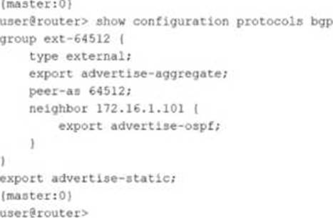
Referring to the exhibit, which export policy applies to the BGP neighbor 172.16.1.101?
- A . the advertise-aggregate policy
- B . the advertise-ospf policy
- C . the advertise-static policy
- D . the BGP default export policy
B
Explanation:
In Junos BGP configuration, export policy can be applied at multiple levels, including the BGP group level and the individual neighbor level. When an export policy is configured directly under a specific neighbor, that policy is explicitly associated with advertisements sent to that neighbor and is therefore the policy that applies to that neighbor. In the exhibit, neighbor 172.16.1.101 has an export statement configured within the neighbor stanza, and that statement references the advertise-ospf policy. This is the most specific policy attachment in the configuration because it is tied to a single peer rather than to the entire group or the whole BGP process.
Group-level export policies, such as advertise-aggregate configured under the group, apply broadly to all neighbors in that group unless a neighbor has additional neighbor-specific policy. A BGP-level export policy configured outside the group applies as a more general export policy scope. However, the question asks which export policy applies to the specific neighbor, and the correct selection is the neighbor-specific export policy that is explicitly configured for that peer.
Operationally, this allows data center engineers to advertise different route sets to different peers, for example exporting OSPF-derived infrastructure routes to one neighbor while exporting aggregates or static routes to another, all while keeping a consistent group template for shared settings such as peer AS and session type.
How does a Layer 2 switch create an Ethernet switching table? Choose one.
- A . It records the source MAC address of the received frames.
- B . It downloads the table from the root bridge of the STP domain.
- C . It uses a Layer 2 firewall filter.
- D . It records the destination MAC address of the received frames.
A
Explanation:
A Layer 2 switch builds its Ethernet switching table through a learning process based on the source MAC addresses of incoming frames. When a frame arrives on an interface within a VLAN or bridge domain, the switch examines the source MAC address and associates it with the ingress interface and VLAN context. If the MAC address is new, the switch creates a new entry; if it already exists but is seen on a different interface, the switch updates the entry to reflect the new location. This dynamic learning is fundamental to efficient unicast forwarding and is why option A is correct.
Once the switch has learned MAC-to-port mappings, it can forward subsequent frames destined to those MAC addresses as known unicast out the specific egress interface rather than flooding them. If the destination MAC is unknown, the switch typically floods the frame within the VLAN or bridge domain to discover the correct destination. When the destination replies, the switch learns that MAC as a source, completing the learning cycle.
Spanning Tree Protocol does not provide a MAC table and there is no concept of downloading an Ethernet switching table from a root bridge. STP’s role is loop prevention and topology control at Layer 2, not MAC learning distribution. Firewall filters can enforce policy but do not create the switching table. Recording destination MAC addresses would not correctly learn endpoint locations because the destination can be unknown when the first frames are sent; source learning is reliable because every received frame carries the sender’s MAC address.
Which state in the adjacency process do OSPF routers check the MTU size?
- A . Init
- B . Exchange
- C . Done
- D . ExStart
B
Explanation:
In OSPF, routers exchange link-state information in different stages to establish full adjacency. The MTU size is checked during the Exchange state.
Step-by-Step Breakdown:
In a five-stage IP fabric, what is the role of the superspine layer?
- A . It ensures that every leaf device has a physical connection to every spine device in the five-stage IP fabric.
- B . It establishes a common BGP autonomous system that combines multiple three-stage IP fabric spine-and-leaf nodes into one autonomous system.
- C . It creates a Layer 2 underlay network between the spine nodes and leaf nodes in the five-stage IP fabric.
- D . It interconnects the spine layers in different three-stage IP fabric pods in a data center at the same site or across different sites.
D
Explanation:
A five-stage IP fabric is typically used when a single pod, even with a three-stage design, cannot meet overall scale requirements for port count, bandwidth, or modular growth. In this model, the data center is built from multiple fabric pods, where each pod is commonly a three-stage topology that includes leaf switches and one or more spine layers. The superspine layer provides the interconnect that ties these pods together into a larger fabric. Functionally, superspines create high-capacity, routed connectivity between the spine layers of different pods so that endpoints in any pod can reach endpoints in any other pod using consistent Layer 3 forwarding principles and equal-cost multipath behavior where applicable.
Option D is correct because the superspine layer is the aggregation and inter-pod transit layer. It does not exist to force every leaf to connect to every spine across the entire multi-pod deployment. That full mesh property is preserved within a pod, not across the entire site at extreme scale. The superspine layer also does not create a Layer 2 underlay; modern fabrics use a routed underlay to avoid spanning tree limitations and to enable deterministic multipathing. Finally, the superspine layer is not defined by creating a single common BGP autonomous system; autonomous system design is a policy choice, while the superspine role is a physical and logical interconnection function between pods.
Which protocol is supported in an IP fabric underlay network? Choose one.
- A . RSTP
- B . EVPN
- C . VXLAN
- D . EBGP
D
Explanation:
An IP fabric underlay is the routed foundation of a modern leaf-spine data center. Its purpose is to provide scalable, deterministic Layer 3 reachability between all fabric nodes, typically using point-to-point routed links between leaves and spines. In this design, EBGP is commonly used as an underlay routing protocol because it scales well, supports clear policy boundaries, and enables fast convergence and operational simplicity. Each leaf forms EBGP sessions to each spine, advertising loopback addresses and link subnets so that overlay endpoints and control plane services can reach one another reliably.
RSTP is a Layer 2 spanning tree mechanism and is not the standard protocol for a routed underlay. EVPN is an overlay control plane used to distribute tenant reachability and multihoming information; it is not the underlay routing protocol itself. VXLAN is a data plane encapsulation used by the overlay to transport Layer 2 segments across a Layer 3 fabric; it also is not the underlay routing protocol.
In Juniper data center architectures, the underlay is intentionally kept simple and purely routed, while overlays such as EVPN VXLAN deliver multi-tenant Layer 2 and Layer 3 services on top of that underlay. EBGP fits the underlay requirement among the provided options.
You want to enable routing between VLAN 10 and VLAN 20.
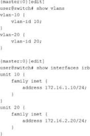
Which two configuration statements must be included in the configuration shown in the exhibit to accomplish this task? Choose two.
- A . set vlans default vlan-id 20
- B . set vlans vlan-10 l3-interface irb.10
- C . set vlans vlan-20 l3-interface irb.20
- D . set vlans default vlan-id 10
B, C
Explanation:
Inter-VLAN routing on Junos switching platforms is typically implemented by associating each VLAN or bridge domain with an IRB interface that provides the Layer 3 gateway for that VLAN. In the exhibit, VLAN 10 and VLAN 20 are defined with vlan-id values, and IRB logical units 10 and 20 already have IPv4 addresses assigned. However, the VLAN definitions do not yet reference the IRB interfaces. Without that association, hosts in the VLANs have no routed gateway on the switch, and the switch cannot perform Layer 3 forwarding between the two VLAN subnets.
To enable routing, each VLAN must include an l3-interface statement that binds the VLAN to the corresponding IRB logical unit. Adding l3-interface irb.10 under vlan-10 makes irb.10 the default gateway interface for VLAN 10 and enables the device to route traffic sourced from that VLAN.
Adding l3-interface irb.20 under vlan-20 does the same for VLAN 20. Once both VLANs are bound to their IRB interfaces, the switch can route packets between 172.16.1.0/24 and 172.16.2.0/24 using its routing table, while still switching Layer 2 traffic within each VLAN.
The default VLAN settings are unrelated to enabling routing between these two specific VLANs. They control the behavior of the default VLAN, not the creation of Layer 3 gateways for VLAN 10 and VLAN 20.
You are creating a static route with a next hop that is not directly connected.
Which feature should be used to accomplish this task?
- A . install
- B . resolve
- C . qualified next hop
- D . retain
B
Explanation:
In Junos, a static route normally expects its next hop to be directly reachable on a connected interface. When the configured next hop is not directly connected, the router must determine how to reach that next hop using an existing route in the routing table. The resolve feature provides this behavior by allowing Junos to recursively resolve the configured static next hop through another route, such as an IGP learned route, a directly connected route to an intermediate device, or even another static route. Once the system can resolve the next hop to a usable outgoing interface and a final forwarding next hop, the static route becomes active and can be installed in the forwarding table.
This is common in data center environments where you want to point a static route at a loopback address, a service node address, or a next hop that is reachable through the fabric underlay rather than a directly connected subnet. With resolve enabled, the static route’s validity follows the reachability of the recursive path. If the supporting route used for resolution disappears, the static route is withdrawn, helping avoid blackholing traffic toward an unreachable next hop.
The qualified next hop feature is used to define primary and backup next hops with different preferences for the same static route, not to solve indirect reachability by itself. The install and retain options influence route installation and retention behaviors but do not provide recursive resolution of a non-direct next hop.
Which two actions are needed to advertise OSPF routes to BGP neighbors? Choose two.
- A . Create a policy to match and accept the OSPF routes.
- B . Apply the policy to the BGP group as an export policy.
- C . Create a policy to match and accept the BGP routes.
- D . Apply the policy to the BGP group as an import policy.
A, B
Explanation:
To advertise OSPF-learned routes to BGP neighbors on Junos, you must explicitly control route redistribution using policy. Junos does not automatically redistribute routes between routing protocols simply because both protocols are enabled. Instead, you create a routing policy that matches the routes you intend to export, in this case routes whose protocol origin is OSPF. The policy must accept those matched routes so they become eligible for advertisement.
After the policy is created, you must apply it as an export policy under the relevant BGP group or under the BGP protocol hierarchy, depending on your design. Export policy controls what your router sends to BGP peers. When the export policy accepts OSPF routes, Junos advertises those routes to the BGP neighbors in that group, subject to any additional BGP constraints such as next-hop handling, route families, and any peer-specific policy terms.
Creating a policy to match and accept BGP routes is not required for this goal because that would influence what routes are imported into your routing table from BGP, not what you export. Likewise, applying a policy as a BGP import policy affects received routes, not OSPF-to-BGP redistribution. In data center fabrics, this policy-driven approach prevents unintended route leakage and keeps redistribution tightly scoped to the prefixes that must be carried between domains.
You want to advertise the network configured on an interface as an OSPF internal route. You do not want this interface to participate in your OSPF domain.
Which OSPF parameter must you use in this scenario?
- A . passive
- B . interface-type
- C . strict-bfd
- D . link-protection
A
Explanation:
In Junos OSPF, the passive setting is used when you want the prefix on an interface to be advertised into OSPF, but you do not want the interface to form OSPF neighbor adjacencies or send OSPF Hello packets. This is a common data center requirement for server-facing, management, or loopback-related interfaces where you want the subnet to be reachable through the routing domain, but there is no OSPF-capable neighbor on that link. By making the interface passive, the router still includes the connected network in OSPF as an internal route, so other routers learn how to reach that subnet. At the same time, the interface does not participate in adjacency formation, which reduces unnecessary protocol chatter and eliminates the risk of accidentally forming neighbors on an untrusted or unintended segment.
The other options do not meet the requirement. Interface-type changes the OSPF network type behavior, such as broadcast or point-to-point, but it does not stop adjacency formation while still advertising the network. Strict-bfd relates to failure detection behavior when BFD is used with routing protocols and does not control whether OSPF forms neighbors. Link-protection is related to fast reroute and protection mechanisms, not suppressing OSPF adjacency on an interface.