
Practice Free 350-501 Exam Online Questions
Refer to the exhibit:
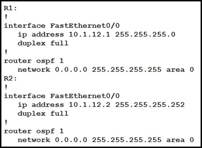
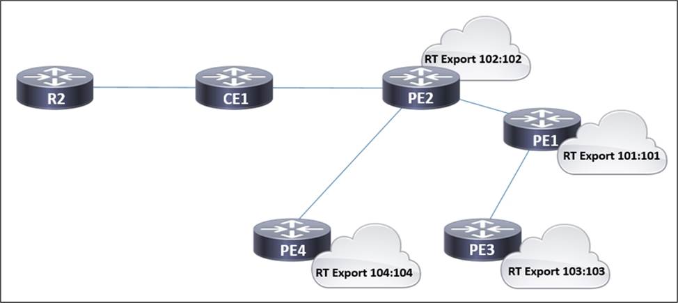
R1 and R2 are directly connected with Fast Ethernet interfaces and have the above configuration applied OSPF adjacency is not formed.
When the debug ip ospf hello command is issued on R1. these log messages are seen.

Which command can be configured on routers R1 and R2 on fO/O interfaces to form OSPF adjacency?
- A . ip ospf network non-broadcast
- B . ip ospf network point-to- multipoint non-broadcast
- C . ip ospf network point-to-point
- D . ip ospf network broadcast
C
Explanation:
The OSPF adjacency issue between R1 and R2 is likely due to mismatched OSPF network types or hello/dead interval settings. The command ip ospf network point-to-point is used on point-to-point network types, which do not require matching hello/dead intervals, thus allowing OSPF adjacency to form even if these intervals are mismatched on the two routers.
Reference: = Implementing and Operating Cisco Service Provider Network Core Technologies course materials.
Refer to the exhibit.
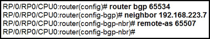
An engineer is securing a customer’s network.
Which command completes this configuration and the engineer must use to prevent a DoS attack?
- A . neighbor ebgp-multihop
- B . ebgp-multihop
- C . ttl-security
- D . neighbor-ttl-security
C
Explanation:
The TTL security mechanism is used to protect a router from receiving BGP sessions that are not originated from the expected peer. It drops incoming TCP segments whose TTL value is not equal to or greater than the expected minimum value, thus helping in preventing DoS attacks that could be initiated from an unauthorized source pretending to be a legitimate BGP peer.
Reference: = Implementing and Operating Cisco Service Provider Network Core Technologies
A customer site is being connected to a Frame Relay network via a T1 link. The customer has a contract for 512 kbps service with a Tc value of 125 ms. Under peak line conditions, customer traffic can reach four times the contracted speed.
Which QoS configuration must the service provider implement to limit the customer to the contracted values?
A)
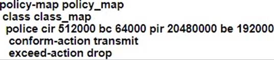
B)
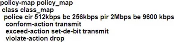
C)

D)
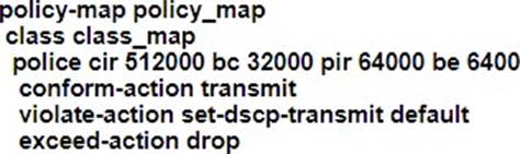
- A . Option A
- B . Option B
- C . Option C
- D . Option D
B
Explanation:
The service provider must implement a QoS configuration that includes traffic policing to enforce the contracted bandwidth limits.
Option B is the correct choice because it specifies a committed information rate (CIR) of 512 kbps, which matches the customer’s contracted rate. The configuration also includes a burst size that accommodates the Tc value of 125 ms, allowing
for brief periods of higher traffic without dropping packets. This setup ensures that under peak conditions, any traffic exceeding the contracted rate is either marked or dropped, thus preventing the customer from exceeding the agreed-upon bandwidth.
Reference: = For more detailed information on QoS configurations for Frame Relay networks, refer to the Implementing and Operating Cisco Service Provider Network Core Technologies (SPCOR) course materials, which cover the principles of traffic policing and shaping in service provider environments
Refer to the exhibit.
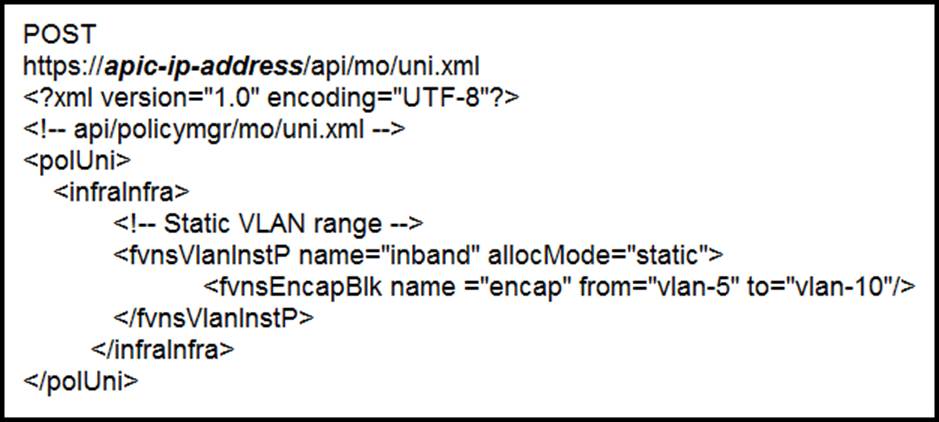
What does the script configure?
- A . a VLAN namespace
- B . selectors for the in-band management
- C . a physical domain
- D . a static VLAN
D
Explanation:
The script in the exhibit is for configuring a static VLAN (Option D). The XML configuration specifies a static VLAN range with “allocMode=‘static’”, indicating that VLAN IDs are assigned manually, not dynamically.
Reference: = These explanations are derived from the concepts outlined in the Cisco Service Provider source book, specifically the “Implementing and Operating Cisco Service Provider Network Core Technologies” course materials,
Refer to the exhibit.
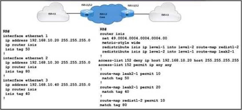
A network engineer with an employee ID 4402:98:032 is setting up an IS-IS network with these requirements:
• Routes with a tag of 80 and IP prefixes other than 192.168.10.20/24 must be redistributed from Level 1 into Level 2
• Route leaking must be configured from Level 2 into the Level 1 domain for routes that are tagged with only 50 or 40
Which configuration must be implemented on RB to meet the requirements?
- A . Add match tag 80 in route-map Ieak2-1
- B . DUMPS Add match ip address 152 in route-map redist1-2
- C . Remove match tag 40 from route-map Ieak2-1
- D . Change match tag 80 to match tag 50 in route-map redist1-2.
B
Explanation:
The requirement is to redistribute routes with a tag of 80 and IP prefixes other than 192.168.10.20/24 from Level 1 into Level 2, and also to configure route leaking from Level 2 into the Level 1 domain for routes that are tagged with only 50 or 40.
Option B, “Add match ip address 152 in route-map redist1-2”, meets the first requirement as it allows all IP prefixes except for the specified one (192.168.10.20/24) to be redistributed from Level-1 to Level-2 when they have a tag of 80.
Reference: Implementing and Operating Cisco Service Provider Network Core Technologies (SPCOR v1.0); Cisco Training & Certifications
How does SR policy operate in Segment Routing Traffic Engineering?
- A . An SR policy for color and endpoint is deactivated at the headend as soon as the headend learns a valid candidate path for the policy.
- B . When "invalidation drop" behavior occurs, the SR policy forwarding entry is removed and the router drops all traffic that is steered into the SR policy.
- C . When a set of SID lists is associated with the SR policy designated path, traffic steering is ECMP-based according to the qualified cost of each SID-list.
- D . An active SR policy installs a BSID-keyed entry in the forwarding table to steer the packets that match the entry to the SR policy SID-list.
Refer to the exihibit.
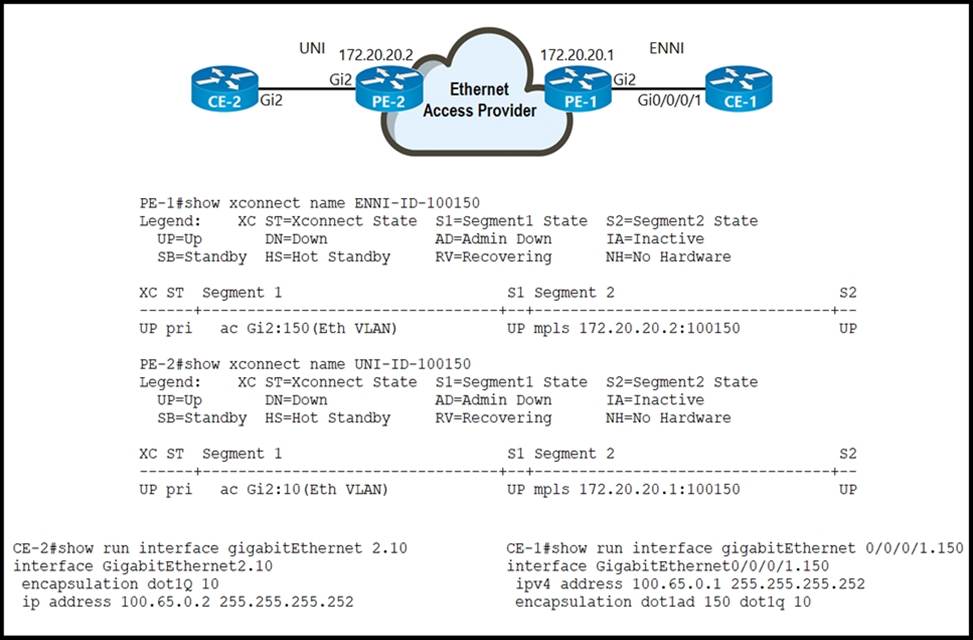
An Ethernet access provider is configuring routers PE-1 and PE-2 to provide E-Access EVPL service between UNI and ENNI. ENNI service multiplexing is based on 802.1ad tag 150, and service-multiplexed UNI is based on 802.1q tag 10.
Which EFP configurations must the provider implement on PE-1 and PE-2 to establish end-to-end connectivity between CE-1 and CE-2?
- A . On PE-1:
interface GigabitEthernet2
service instance 100 ethernet
encapsulation dot1ad 150
rewrite ingress tag pop 1 symmetric
On PE-2:
interface GigabitEthernet2
service instance 2 ethernet
encapsulation dot1q 10 - B . On PE-1:
interface GigabitEthernet2
service instance 100 ethernet
encapsulation dot1q 150
rewrite ingress tag pop 1 symmetric
On PE-2:
interface GigabitEthernet2
service instance 2 ethernet
encapsulation dot1q 10 - C . On PE-1:
interface GigabitEthernet2
service instance 100 ethernet
encapsulation dot1ad 150 dot1q 10
rewrite ingress tag pop 2 symmetric
On PE-2:
interface GigabitEthernet2
service instance 2 ethernet
encapsulation dot1q 10 - D . On PE-1:
interface GigabitEthernet2
service instance 100 ethernet
encapsulation dot1ad 150
rewrite ingress tag pop 1 symmetric
On PE-2:
interface GigabitEthernet2
service instance 2 ethernet
encapsulation dot1q 10
rewrite ingress tag pop 1 symmetric
Refer to the exhibit.
In the service provider network, routers PE1, PE2, and PE4 have access to the internet and provide access to customer networks. Router PE3 is used for access to other customer systems. In accordance with a new SLA, an engineer is updating settings on this network so that router CE1 accesses the internet via PE1 instead of PE2.
Which two tasks must the engineer perform to complete the process? (Choose two.)
- A . On PE1, configure the internet VRF with import route target 102:102.
- B . On PE1 and PE4, configure the internet VRF with import route targets 102:102 and 104:104.
- C . On PE2, configure the internet VRF with import route target 102:102.
- D . On PE2 and PE3, configure the internet VRF with import route target 101:101.
- E . On PE2, configure the CE1 VRF with import route target 101:101.
AE
Explanation:
https://www.cisco.com/c/en/us/support/docs/mpls-vpns/multiprotocol-label-switching-mpls/23986-mpls-vpns-config-example.html
https://www.cisco.com/c/en/us/td/docs/ios-xml/ios/mp_l3_vpns/configuration/15-mt/mp-l3-vpns-15-mt-book/mp-bgp-mpls-vpns.html
Refer to the exhibit.
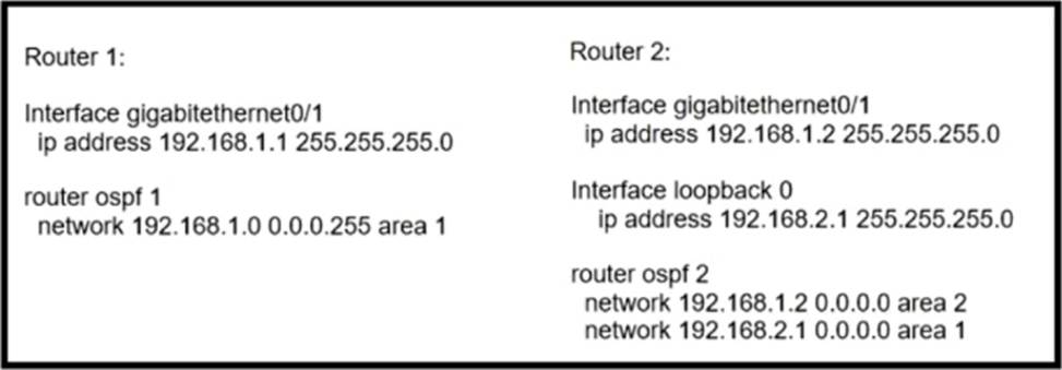
Router 1 is missing the route for the router 2 loopback 0.
What should the engineer change to fix the problem?
- A . the area numbers on Router 1 and Router 2 to be similar
- B . the wildcard mask network statement in OSPF of Router 2
- C . Router 1 to be an ABR
- D . the hello timers on Router 1 and Router 2 to be different
A
Explanation:
The issue with Router 1 missing the route for Router 2’s loopback 0 is likely due to the routers being configured in different OSPF areas. For OSPF to properly exchange routing information, routers within the same network should be configured in the same area. Therefore, the engineer should change the area numbers on Router 1 and Router 2 to be the same, ensuring they can exchange routes, including the route for Router 2’s loopback 0.
Reference: Implementing and Operating Cisco Service Provider Network Core Technologies (SPCOR) documentation and study materials.
Refer to the exhibit.
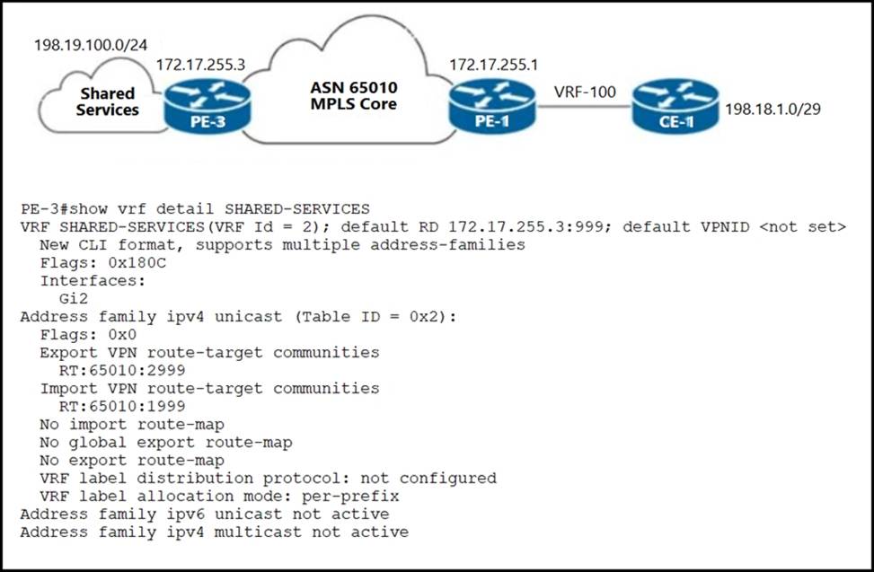
An ISP provides shared VoIP Extranet services to a customer in VRF-100 with these settings:
✑ The VoIP services are hosted in the 198.19.100.0/24 space.
✑ The customer has been assigned the 198.18.1.0/29 IP address block.
✑ VRF-100 is assigned import and export route target 65010:100.
Which configuration must the engineer apply to PE-1 to provision VRF-100 and provide access to the shared services?
- A . vrf definition VRF-100
rd 172.17.255.1:100
!
address-family ipv4
export map VRF-100-EXPORT
import map VRF-100-IMPORT
exit-address-family
!
route-map VRF-100-EXPORT permit 10
match ip address prefix-list VRF-100-ALLOWED-EXPORT
set extcommunity rt 65010:100 65010:2999
route-map VRF-100-EXPORT permit 20
set extcommunity rt 65010:100
!
route-map VRF-100-IMPORT permit 10
match extcommunity VRF-100-RT SHARED-SERVICES
!
ip extcommunity-list standard SHARED-SERVICES permit rt 65010:1999
ip extcommunity-list standard VRF-100-RT permit rt 65010:100
ip prefix-list VRF-100-ALLOWED-EXPORT seq 5 permit 198.18.1.0/29 - B . vrf definition VRF-100
rd 172.17.255.1:100
!
address-family ipv4
export map VRF-100-EXPORT
route-target import 65010:100
route-target import 65010:2999
exit-address-family
!
route-map VRF-100-EXPORT permit 10
match ip address prefix-list VRF-100-ALLOWED-EXPORT
set extcommunity rt 65010:100 65010:1999
route-map VRF-100-EXPORT permit 20
set extcommunity rt 65010:100
!
ip prefix-list VRF-100-ALLOWED-EXPORT seq 5 permit 198.18.1.0/29 - C . vrf definition VRF-100
rd 172.17.255.1:100
!
address-family ipv4
export map VRF-100-EXPORT
route-target import 65010:100
route-target import 65010:1999
exit address-family
!
route-map VRF-100-EXPORT permit 10
match ip address prefix-list VRF-100-ALLOWED-EXPORT
set extcommunity rt 65010:100 65010:2999
route-map VRF-100-EXPORT permit 20
set extcommunity r 65010:100
!
ip prefix-list VRF-100-ALLOWED-EXPORT seq 5 permit 198.18.1.0/29 - D . vrf definition VRF-100
rd 172.17.255.1:100
!
address-family ipv4
route-target export 65010:100
route-target export 65010:1999
route-target import 65010:100
route-target import 65010:2999
exit-address-family