
Practice Free 3V0-25.25 Exam Online Questions
An administrator must provide North/South connectivity for a VPC. The fabric exposes a distributed external VLAN across all ESX hosts. But, the only BGP peer to the core is on a VLAN only accessible on the Edge Cluster.
Which design is required?
- A . Use a VPC Tier-0 Gateway in active/active mode with distributed eBGP peering.
- B . Distributed Transit Gateway with an EVPN route reflector on the transport nodes.
- C . Centralized Transit Gateway on the Edge Cluster.
- D . Deploy a Provider Tier-1 with BGP and connect the VPC Transit Gateway via route leaking.
C
Explanation:
Comprehensive and Detailed 250 to 350 words of Explanation From VMware Cloud Foundation (VCF) documents:
In a VMware Cloud Foundation (VCF) environment utilizing the Virtual Private Cloud (VPC) model, North/South connectivity is managed by the Transit Gateway (TGW). The TGW acts as the bridge between the VPC-internal networks and the provider-level physical network.
The scenario presents a specific constraint: while an external VLAN exists across all hosts, the actual BGP peering point (the interface to the physical core routers) is restricted to the NSX Edge Cluster. In NSX terminology, when a gateway or service must be anchored to specific Edge Nodes to access physical network services―such as BGP peering, NAT, or stateful firewalls―it must be configured as a Centralized component.
A Centralized Transit Gateway (Option C) is instantiated on the Edge nodes. This allows the TGW to participate in the BGP session with the core routers on the VLAN that is only accessible to those Edges. The TGW then handles the routing for the VPC’s internal segments. Traffic from the ESXi transport nodes (East-West) travels via the Geneve overlay to the Edge nodes, where it is then routed North-South by the Centralized TGW using the physical BGP peer.
Option A is incorrect because "distributed eBGP peering" would require every ESXi host to have peering capabilities, which contradicts the constraint.
Option B involves EVPN, which is a significantly more complex and different architecture than what is required for standard VPC North/South access.
Option D is an unnecessarily complex routing design that is not the standard VCF/VPC implementation pattern. Thus, the use of a Centralized Transit Gateway on the Edge cluster is the verified design requirement to bridge the gap between the overlay VPC and the localized BGP peering point.
An administrator is investigating packet loss reported by workloads connected to VLAN segments in an NSX environment. Initial checks confirm:
• All VMs are powered on
• VLAN segment IDs are consistent across transport nodes
• Physical switch configurations are correct.
Which two NSX tools can be used to troubleshoot packet loss on VLAN Segments? (Choose two.)
- A . Flow Monitoring
- B . Traceflow
- C . Packet Capture
- D . Activity Monitoring
- E . Live Flow
B, C
Explanation:
Comprehensive and Detailed 250 to 350 words of Explanation From VMware Cloud Foundation (VCF) documents:
In a VMware Cloud Foundation (VCF) environment, troubleshooting packet loss requires tools that can provide visibility into both the logical and physical paths of a packet. When dealing specifically with VLAN segments (as opposed to Overlay segments), the traffic does not leave the host encapsulated in Geneve; instead, it is tagged with a standard 802.1Q header.
Traceflow is the primary diagnostic tool within NSX for identifying where a packet is being dropped. It allows an administrator to inject a synthetic packet into the data plane from a source (such as a VM vNIC) to a destination. The tool then reports back every "observation point" along the path, including switching, routing, and firewalling. If a packet is dropped by a Distributed Firewall (DFW) rule or a physical misconfiguration that wasn’t caught initially, Traceflow will explicitly state at which stage the packet was lost.
Packet Capture is the second essential tool. NSX provides a robust, distributed packet capture utility that can be executed from the NSX Manager CLI or UI. This tool allows administrators to capture traffic at various points, such as the vNIC, the switch port, or the physical uplink (vmnic) of the ESXi Transport Node. By comparing captures from different points, an administrator can determine if a packet is reaching the virtual switch but failing to exit the physical NIC, or if return traffic is reaching the host but not the VM.
Options like Flow Monitoring and Live Flow are excellent for observing traffic patterns and session statistics (IPFIX), but they are less effective for pinpointing the exact cause of "packet loss" compared to the granular, packet-level analysis provided by Traceflow and Packet Capture. Activity Monitoring is typically used for endpoint introspection and user-level activity, which is irrelevant to Layer 2/3 packet loss troubleshooting.
A large multinational corporation is seeking proposals for the modernization of a Private Cloud environment.
The proposed solution must meet the following requirements:
• Support multiple data centers located in different geographic regions.
• Provide a secure and scalable solution that ensures seamless connectivity between data centers and different departments.
Which three NSX features or capabilities must be included in the proposed solution? (Choose three.)
- A . NSX Edge
- B . AVI Load Balancer
- C . vDefend
- D . Virtual Private Cloud (VPC)
- E . Centralized Network Connectivity
- F . NSX L2 Bridging
A, C, D
Explanation:
Comprehensive and Detailed 250 to 350 words of Explanation From VMware Cloud Foundation (VCF) documents:
In a modern VMware Cloud Foundation (VCF) architecture, particularly when addressing the needs of a multinational corporation with geographically dispersed data centers, the solution must prioritize multi-tenancy, security, and consistent delivery. The integration of NSX within VCF provides these core pillars.
First, the NSX Edge is a foundational requirement for any multi-site or modern cloud environment. It serves as the bridge between the virtual overlay network and the physical world. In a multi-region deployment, NSX Edges facilitate North-South traffic and are essential for supporting features like Global Server Load Balancing (GSLB) or site-to-site connectivity. Without the Edge, the software-
defined data center (SDDC) cannot communicate with external networks or peer via BGP with physical routers.
Second, vDefend (formerly known as NSX Security) provides the advanced security framework required for a "secure and scalable" environment. This includes Distributed Firewalling (DFW), Distributed IDS/IPS, and Malware Prevention. For a corporation with different departments, vDefend allows for micro-segmentation, ensuring that a security breach in one department’s segment cannot move laterally to another. This is critical for meeting compliance and isolation requirements across global regions.
Third, the Virtual Private Cloud (VPC) model is the cornerstone of the latest VCF 9.0 and 5.x architectures. It enables the "scalable solution" for different departments by providing a self-service consumption model. Each department can manage its own isolated network space, including subnets and security policies, without needing deep networking expertise or constant tickets for the central IT team. This abstraction simplifies management across multiple data centers and allows for consistent application of policies regardless of the physical location.
While AVI Load Balancer and Centralized Network Connectivity are valuable, they are often considered add-ons or outcomes rather than the core architectural features that define the multi-tenant, secure, and geographically distributed nature of a modern VCF private cloud modernization project.
DRAG DROP
An administrator is responsible for the management of a VMware Cloud Foundation (VCF) Fleet that consists of two VCF instances that are located in different physical locations. The administrator has been tasked with configuring a VPN between the two locations and has been tasked with identifying the two supported NSX Gateway configurations for an IPSec VPN.
Drag and drop two items from the list of Possible Configurations into the list of Supported Configurations in any order. (Choose two.)
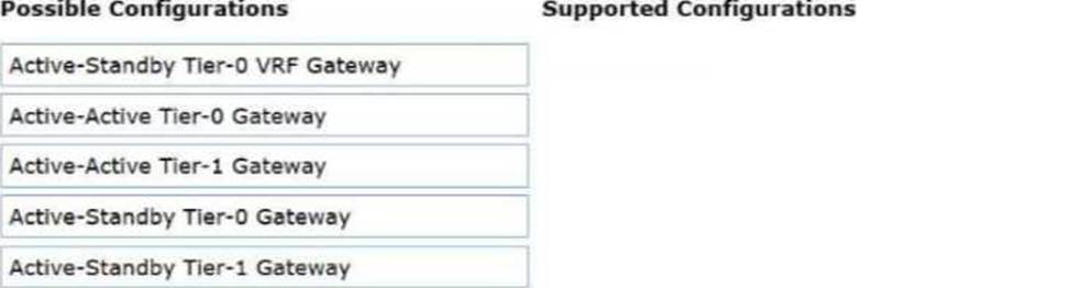
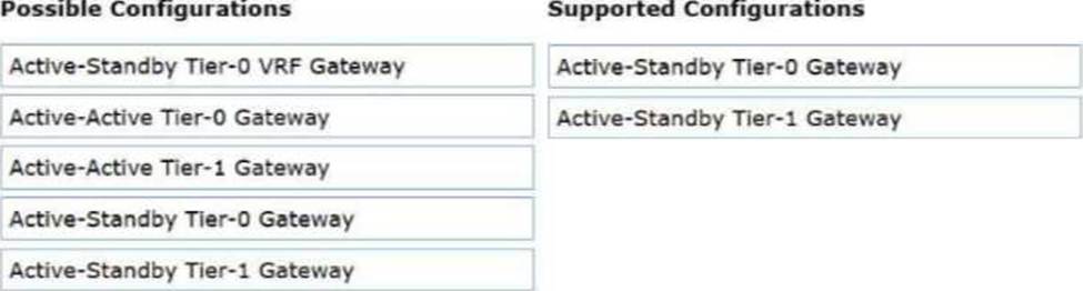
Explanation:
Active-Standby Tier-0 Gateway
Active-Standby Tier-1 Gateway
In a VMware Cloud Foundation (VCF) multi-site or multi-instance architecture, established via NSX Federation, secure connectivity between sites is often achieved through IPSec VPN. IPSec VPN is considered a stateful service within the NSX networking stack.
Stateful services―which also include NAT and Load Balancing―require a centralized point of processing to maintain the security association (SA) and session state tables. In the NSX gateway architecture, this necessitates the presence of a Service Router (SR) component. For stateful consistency and to avoid session disruption that would occur if asymmetric traffic were processed by different nodes, these gateways must operate in an Active-Standby high-availability mode.
According to the "NSX-T Data Center VPN Configuration Guide," IPSec VPN services can be deployed on either the provider tier (Tier-0 Gateway) or the tenant tier (Tier-1 Gateway). When configured on a Tier-0 gateway, the VPN typically provides broad connectivity between the physical infrastructure of two sites. When configured on a Tier-1 gateway, it often provides targeted connectivity for a specific project or department’s workload segments.
Configurations involving Active-Active gateways (whether Tier-0 or Tier-1) do not support the native NSX IPSec VPN service because the ECMP (Equal Cost Multi-Pathing) nature of Active-Active mode could lead to packets belonging to the same VPN tunnel being processed by different Edge nodes, which cannot share the real-time encryption state. Therefore, for an administrator to successfully implement a cross-location VPN in a VCF Fleet, they must ensure the target gateway―be it Tier-0 or Tier-1―is deployed in Active-Standby mode.
An architect needs to allow users to deploy multiple copies of a test lab with public access to the internet. The design requires the same machine IPs be used for each deployment.
What configuration will allow each lab to connect to the public internet?
- A . Configure DNAT rules on the Tier-1 gateway.
- B . Configure isolation on the NSX segment.
- C . Configure firewall rules to isolate the traffic going to the public internet.
- D . Configure SNAT rules on the Tier-0 gateway.
D
Explanation:
Comprehensive and Detailed 250 to 350 words of Explanation From VMware Cloud Foundation (VCF) documents:
This scenario describes a classic "Overlapping IP" or "Fenced Network" challenge in a private cloud environment. In many development or lab use cases, users need to deploy identical environments where the internal IP addresses (e.g., 192.168.1.10) are the same across different instances to ensure application consistency.
To allow these identical environments to access the public internet simultaneously without causing an IP conflict on the external physical network, Source Network Address Translation (SNAT) is required. According to VCF and NSX design best practices, the Tier-0 Gateway is the most appropriate place for this translation when multiple tenants or labs need to share a common pool of external/public IP addresses.
When a VM in Lab A sends traffic to the internet, the Tier-0 Gateway intercepts the packet and replaces the internal source IP with a unique public IP (or a shared public IP with different source ports). When Lab B (which uses the same internal IP) sends traffic, the Tier-0 Gateway translates it to a different unique public IP (or the same shared public IP with different ports). This ensures that return traffic from the internet can be correctly routed back to the specific lab instance that initiated the request.
Option A (DNAT) is used for inbound traffic (allowing the internet to reach the lab), which doesn’t solve the outbound connectivity requirement for overlapping IPs.
Option B (Isolation) would prevent communication entirely.
Option C (Firewall) controls access but does not solve the routing conflict caused by identical IP addresses. Thus, SNAT rules on the Tier-0 gateway are the verified solution for providing internet access to overlapping lab environments.
An administrator is troubleshooting an issue where workloads connected to a Tier-1 Gateway named T1-App can no longer reach external North/South destinations.
• The Tier-1 is connected to an Active/Standby Tier-0 Gateway named T0-Prod.
Symptoms observed:
• VMs on segments attached to T1-App can ping each other.
• VMs on T1-App cannot reach any external IP outside T0-Prod.
• From a VM on the segment, ping to the T1-App Distributed Router (DR) IP succeeds.
• Ping from the VM to the T1-App Service Router (SR) fails.
• The Edge cluster hosting the T1-App SR shows both Edge nodes Up and Healthy.
• No failover has occurred ― the same Edge node is still shown as Active for T1-App.
What is the most likely cause of this issue?
- A . The overlay network between DR and SR has an MTU mismatch.
- B . Route advertisement from T1-App to T0-Prod for 100.64.x.x/31 is disabled.
- C . Static default route is missing on the Tier-1 DR component.
- D . Localized control plane is enabled on the Tier-1 causing the SR to remain admin-down.
A
Explanation:
Comprehensive and Detailed 250 to 350 words of Explanation From VMware Cloud Foundation (VCF) documents:
In the NSX multi-tier routing architecture used by VCF, a Tier-1 Gateway is composed of two primary components: the Distributed Router (DR) and the Service Router (SR). The DR runs as a kernel module on every ESXi host in the transport zone, facilitating East-West traffic. The SR resides on the NSX Edge nodes and provides centralized services like North-South connectivity and stateful services.
Communication between the DR (on the ESXi host) and the SR (on the Edge node) occurs over a hidden internal segment known as the Router Link. This link is encapsulated in Geneve just like VM-to-VM traffic. When a VM attempts to reach an external destination, the packet is first routed by the DR on the local host. The DR then encapsulates the packet and sends it across the overlay to the TEP (Tunnel Endpoint) of the Edge node hosting the SR.
If the MTU (Maximum Transmission Unit) is misconfigured on the physical network or the virtual switches, large encapsulated packets will be dropped. However, small packets (like pings between VMs on the same host) might still succeed. In this scenario, the fact that the VM can ping the local DR but cannot reach the SR―and therefore cannot reach external networks―points to a failure in the transport between the host and the Edge.
If the Geneve-encapsulated packet containing the ping request to the SR’s internal interface exceeds the physical network’s MTU, it will fail. Since VCF 5.x/9.0 requires a minimum MTU of 1600 (ideally 9000) for the overlay to account for the Geneve overhead, a mismatch anywhere in the fabric will break the DR-to-SR "backplane" communication. This prevents the Tier-1 from passing any traffic to its Tier-0 uplink, effectively isolating the workloads from North-South traffic.
In an NSX environment, an administrator is observing low throughput and intermittent congestion between the Tier-0 Gateway and the upstream physical routers. The environment was designed for high availability and load balancing, using two Edge Nodes deployed in Active/Active mode. The administrator enables ECMP on the Tier-0 gateway, but the issues persist.
Which action would address low throughput and congestion?
- A . Convert Tier-1 gateways to be edgeless.
- B . Disable NAT on the Tier-0 gateway.
- C . Add an additional vNIC to the NSX Edge node.
- D . Deploy additional Edge nodes.
D
Explanation:
Comprehensive and Detailed 250 to 350 words of Explanation From VMware Cloud Foundation (VCF) documents:
When a VMware Cloud Foundation (VCF) environment experiences North-South congestion at the Tier-0 Gateway, it typically indicates that the processing capacity of the existing NSX Edge Nodes has been reached. In an Active/Active configuration, the Tier-0 gateway utilizes Equal Cost Multi-Pathing (ECMP) to distribute traffic across all available Edge nodes in the cluster.
If a two-node Edge cluster is saturated despite ECMP being enabled, the standard "Scale-Out" procedure is to deploy additional Edge nodes (Option D). NSX supports up to 8 Edge nodes in a single cluster for a Tier-0 gateway. By adding more nodes, the administrator increases the total number of CPU cores dedicated to the DPDK (Data Plane Development Kit) packet processing engine. Each additional node provides more "bandwidth lanes" for the ECMP hash to utilize, effectively multiplying the aggregate throughput capability of the North-South exit point.
Option A is incorrect because "edgeless" Tier-1 gateways (Distributed Routers only) improve East-West performance by keeping traffic on the ESXi hosts, but they do not help with North-South traffic that must eventually hit a Tier-0 Service Router on an Edge.
Option B (Disabling NAT) might reduce CPU overhead slightly, but it doesn’t solve a fundamental capacity bottleneck and is often not an option due to architectural requirements.
Option C (Adding a vNIC) does not increase the underlying compute/DPDK processing power of the Edge VM and can sometimes complicate the load-balancing hash.
In VCF operations, this expansion is handled via the SDDC Manager, which can automate the addition of new Edge nodes to an existing cluster, ensuring they are configured symmetrically with the correct
uplink profiles and BGP peering sessions. This horizontal scaling is the verified method for resolving congestion in high-demand VCF networking environments.
A cloud service provider runs VPCs with differing traffic patterns:
• Some VPCs are generating high, large North/South flows.
• Most of the VPCs generate very little traffic.
The architect needs to optimize Edge data plane resource consumption while ensuring that noisy VPCs do not impact others.
Which optimization satisfies the requirement?
- A . Assign one dedicated Edge node per high-traffic VPC.
- B . Reduce the number of VPCs by consolidating VPCs into shared namespaces.
- C . Convert high-traffic VPCs into VLAN-backed segments attached directly to Tier-0 gateways.
- D . Use multiple Edge clusters and distribute VRF-backed VPCs based on traffic profiles.
D
Explanation:
Comprehensive and Detailed 250 to 350 words of Explanation From VMware Cloud Foundation (VCF) documents:
In a VMware Cloud Foundation (VCF) environment, especially with the architectural evolution in VCF 9.0, the Virtual Private Cloud (VPC) model is the primary way to deliver self-service, isolated networking. The networking performance for North/South traffic―traffic leaving the SDDC for the physical network―is processed by NSX Edge Nodes. These Edge Nodes use DPDK (Data Plane Development Kit) to provide high-performance packet processing, but their resources (CPU and Memory) are finite.
When dealing with "noisy neighbors"―tenants or VPCs that consume a disproportionate amount of throughput―it is critical to isolate their data plane impact. According to the VMware Validated Solutions and VCF Design Guides, the most scalable and efficient way to achieve this is through the use of Multiple Edge Clusters. By creating distinct Edge clusters, an architect can physically isolate the compute resources used for routing.
In this scenario, high-traffic VPCs can be backed by specific VRF (Virtual Routing and Forwarding) instances on a Tier-0 gateway that is hosted on a dedicated high-performance Edge Cluster. Meanwhile, the numerous low-traffic VPCs can share a different Edge Cluster. This "Traffic Profile" based distribution ensures that a spike in traffic within a "heavy" VPC only consumes the DPDK cycles of its assigned Edge nodes, leaving the resources for the "quiet" VPCs untouched.
Option A is incorrect because Edge nodes function in clusters for high availability; assigning a single node creates a single point of failure and is administratively heavy.
Option B reduces the multi-tenancy benefits and doesn’t solve the resource contention at the Edge level.
Option C removes the benefits of the software-defined overlay and VPC consumption model. Therefore, distributing VRF-backed VPCs across multiple Edge clusters based on their expected load is the verified design best practice for optimizing resource consumption while maintaining strict performance isolation in a VCF provider environment.
A sovereign cloud provider has a VMware Cloud Foundation (VCF) stretched Workload Domain across two data centers (AZ1 and AZ2), where site connectivity via Layer 3 is provided by the underlay.
The following NSX details are included in the design:
• Each site must host its own local NSX Edge Cluster for availability zones.
• Tier-0 gateways must be configured in active/active mode with BGP ECMP to local top-of-rack switches.
• Inter-site Edge TEP traffic must not cross the inter-DC link.
• SDDC Manager is used to automate NSX deployment.
During deployment of the Edge Cluster for AZ2, the SDDC Manager workflow fails because the Edge transport nodes’ TEP IPs are not reachable from the ESXi transport nodes.
Which step ensures correct Edge Cluster deployment in multi-site stretched domains?
- A . Disable the liveness check during Edge deployment in SDDC Manager.
- B . Configure BGP neighbors before deploying the Edge Cluster.
- C . Reuse the TEP IP pool from AZ1.
- D . Create an AZ2-specific Edge TEP IP pool and map it to the AZ2 uplink profile before deploying the Edge Cluster.
D
Explanation:
Comprehensive and Detailed 250 to 350 words of Explanation From VMware Cloud Foundation (VCF) documents:
In a VMware Cloud Foundation (VCF) stretched cluster or Multi-Availability Zone (Multi-AZ) architecture, the networking design must account for the fact that AZ1 and AZ2 typically reside in different Layer 3 subnets. While the NSX Overlay provides Layer 2 adjacency for virtual machines across sites, the underlying Tunnel Endpoints (TEPs) must be able to communicate over the physical Layer 3 network.
According to the VCF Design Guide for Multi-AZ deployments, when stretching a workload domain, each availability zone should have its own dedicated TEP IP Pool. This is because TEP traffic is encapsulated (Geneve) and routed via the physical underlay. If the Edge nodes in AZ2 were to use the same IP pool as AZ1 (Option C), the physical routers would likely encounter routing conflicts or reachability issues, as the subnet for AZ1 would not be natively routable or "local" to the AZ2 Top-of-Rack (ToR) switches.
The failure during the SDDC Manager workflow occurs because the automated "Liveness Check" or "Pre-validation" step attempts to verify that the newly assigned TEP IPs in AZ2 can reach the existing TEPs in the environment. To resolve this and ensure a successful deployment, the administrator must define a unique AZ2-specific IP Pool in NSX. Furthermore, this pool must be associated with an Uplink Profile (or a Sub-Transport Node Profile in VCF 5.x/9.0) that uses the specific VLAN tagged for TEP traffic in the second data center. This ensures that the Edge Nodes in AZ2 are assigned IPs that are valid and routable within the AZ2 underlay, allowing Geneve tunnels to establish correctly to the ESXi hosts in both sites without requiring a stretched Layer 2 physical network for the TEP infrastructure.