
Practice Free JN0-481 Exam Online Questions
A member of your organization made changes to a predefined interface map using Juniper Apstra.
Which two statements are correct in this scenario? (Choose two.)
- A . Changes to interface maps in the global catalog do not affect interface maps that have already been imported into blueprint catalogs
- B . Any changes made to predefined interface maps are discarded when Apstra is upgraded.
- C . Changes made to predefined interface maps will not have an impact on the Apstra software.
- D . Changes to interface maps in the global catalog will raise anomalies that may need to be addressed at the next commit.
AB
Explanation:
According to the Juniper documentation1, an interface map is a configuration template that maps interfaces between logical devices and physical hardware devices (represented with device profiles) while adhering to vendor specifications. An interface map can be either predefined or custom. A predefined interface map is one that ships with Apstra software and supports most qualified Juniper devices. A custom interface map is one that is created by the user to meet specific requirements. An interface map can be stored in either the global catalog or the blueprint catalog. The global catalog contains all the interface maps that are available for use in any blueprint. The blueprint catalog contains the interface maps that are imported from the global catalog and used in a specific blueprint.
When a member of your organization makes changes to a predefined interface map, the following statements are correct:
Changes to interface maps in the global catalog do not affect interface maps that have already been imported into blueprint catalogs. This means that the existing blueprints that use the original version of the interface map will not be impacted by the changes. However, if you want to use the updated version of the interface map in a new or existing blueprint, you need to import it again from the global catalog.
Any changes made to predefined interface maps are discarded when Apstra is upgraded. This means that the changes will not be preserved across different versions of Apstra software. If you want to retain a customized interface map through Apstra upgrades, you need to clone the predefined interface map, give it a unique name, and customize it instead of changing the predefined one directly.
Therefore, the correct answer is A and B. Changes to interface maps in the global catalog do not affect interface maps that have already been imported into blueprint catalogs and any changes made to predefined interface maps are discarded when Apstra is upgraded.
Reference: Edit Interface Map | Apstra 4.2 | Juniper Networks
You have accessed your deployed blueprint and see the banner shown in the exhibit.
![]()
Which two statements are correct in this scenario? (Choose two.)
- A . Devices must be assigned to profiles.
- B . There are changes that are not active on the fabric.
- C . Resources must be assigned to devices.
- D . There are anomalies that must be addressed.
B, D
Explanation:
In Apstra 5.1, the top-level blueprint banner uses tab indicators (colored badges) to summarize blueprint status across areas such as Staged, Uncommitted, Active, and Analytics. The presence of an Uncommitted indicator signifies that there are staged modifications that have not yet been committed and therefore are not part of the active, deployed intent. That directly corresponds to the statement that changes exist which are not active on the fabric.
At the same time, the banner shows an Active indicator in an alarm state, which reflects that the running fabric has issues requiring attention―commonly surfaced as anomalies (for example, configuration deviation, interface/link faults, protocol/session issues, or service-impacting conditions). In Apstra’s operational model, these issues appear as anomalies that operators should investigate and remediate to restore compliance and health. Therefore, the statement that there are anomalies that must be addressed is also correct.
The remaining options are not implied by this banner alone. Device profile assignment and resource assignment are build-time tasks, but their absence is not what the Uncommitted/Active alert indicators are specifically communicating here. The banner is highlighting uncommitted intent changes and active anomalies that affect the deployed blueprint state and assurance posture.
Verified Juniper sources (URLs):
https://www.juniper.net/documentation/us/en/software/apstra5.1/apstra-user-guide/topics/concept/uncommitted.html
https://www.juniper.net/documentation/us/en/software/apstra5.0/apstra-user-guide/topics/topic-map/anomalies-service-active.html
https://cloudlabs.apstra.com/labguide/Cloudlabs/6.0.0/test-drive-guide/lab1-junos-5_blueprints_.html
What are two agent processes that operate within the Juniper Apstra device agent? (Choose two.)
- A . Routing agent
- B . Authentication agent
- C . Telemetry agent
- D . Deployment agent
C, D
Explanation:
In Apstra deployments that use on-box device agents, the agent package installs multiple processes inside the switch’s NOS namespace to provide an isolated runtime environment for Apstra control and telemetry collection. Two of those processes are the Telemetry Agent and the Deployment Agent. The Telemetry Agent is responsible for collecting operational information from the device― such as LLDP neighbor details, routing-related state, and interface information―and sending that telemetry upstream to Apstra. This telemetry is a key input for closed-loop assurance in EVPN-VXLAN fabrics, where Apstra correlates underlay health (interfaces, neighbors, sessions) with overlay services.
The Deployment Agent is responsible for receiving configuration content pushed from Apstra and applying it on the device. In a Junos v24.4 fabric, this is the component that enables Apstra to converge device configuration to the blueprint’s intent (for example, BGP underlay, EVPN signaling, and VXLAN constructs) without requiring manual CLI workflows. Both agents are typically idle most of the time, becoming active when Apstra needs to apply configuration changes or when significant state changes trigger telemetry updates.
Other listed options―“routing agent” and “authentication agent”―are not the named Apstra device-
agent processes described for the on-box agent package in Juniper documentation.
Verified Juniper sources (URLs):
https://www.juniper.net/documentation/us/en/software/apstra4.2/apstra-server-and-security-guide/topics/concept/apstra-device-agents.html
When creating a probe, an operator wants to make it easy to view that probe’s output.
In this scenario, which element must be created to accomplish this task?
- A . A dashboard widget
- B . A predefined probe
- C . A processor
- D . A stage
A
Explanation:
In Apstra IBA, a probe is a directed graph made of stages (data you can inspect) and processors (operations that transform/aggregate data). While stages can be inspected during probe construction, the simplest operational way to make probe results readily consumable by day-2 operators is to publish them through widgets that can be placed on Analytics dashboards. A dashboard widget is the visualization and presentation object that renders either (1) counts of anomalies or (2) the outputs produced by stages and processors in a probe. Creating a widget tied to the probe output means the operator can open a dashboard and immediately see the metric trends, tables, or anomaly indicators without navigating into probe internals.
A predefined probe is optional content (a starting template) and is not required for visibility. Processors and stages are internal probe building blocks, but they do not, by themselves, create an operator-friendly view in the UI. In a Junos v24.4 EVPN-VXLAN fabric, this is especially useful for link utilization, drops, latency signals, or any custom telemetry pipeline: you build the probe logic once, then expose the key results in a widget that persists across operational workflows and can be shared on standardized dashboards for capacity planning and troubleshooting.
Verified Juniper sources (URLs):
https://www.juniper.net/documentation/us/en/software/apstra4.2/apstra-user-guide/topics/concept/widgets.html
https://www.juniper.net/documentation/us/en/software/apstra4.2/apstra-user-guide/topics/topic-map/widget-stage-create.html
https://www.juniper.net/documentation/us/en/software/apstra4.2/apstra-user-guide/topics/concept/probes.html
What does VXLAN use to uniquely label and identify broadcast domains?
- A . VLAN ID
- B . Agent Circuit Identifier (ACI)
- C . Virtual Network Identifier (VNI)
- D . End System Identifier (ESI)
C
Explanation:
In a VXLAN overlay, each Layer 2 broadcast domain (the logical equivalent of a VLAN/bridge domain) is identified by a 24-bit VXLAN Network Identifier (VNI) carried in the VXLAN header. This VNI is what allows the overlay to scale far beyond traditional VLAN space (12-bit VLAN IDs), enabling up to ~16 million distinct segments. In an EVPN-VXLAN data center fabric, Junos v24.4 leaf switches operate as VTEPs and map local bridge domains (often associated with VLANs on server-facing ports) to a VNI. When traffic is sent across the routed underlay, the leaf encapsulates Ethernet frames into VXLAN packets and inserts the VNI so the receiving VTEP can place the frame into the correct broadcast domain on decapsulation.
Apstra 5.1 abstracts this mapping through virtual networks and resource allocation: when you define a VXLAN-based virtual network, Apstra allocates a VNI from the appropriate pool and consistently programs the necessary constructs on all participating leaves. The key point is that VNI is the unique identifier in the VXLAN data plane used to label the broadcast domain across the IP fabric; VLAN IDs may exist locally at the edge for tagging, but the globally significant overlay identifier is the VNI.
Verified Juniper sources (URLs):
https://www.juniper.net/documentation/us/en/software/junos/evpn/topics/topic-map/sdn-vxlan.html
You are using Juniper Apstra to create security policies that create ACLs on the fabric devices.
What are two valid objects that would be used within Apstra in this scenario? (Choose two.)
- A . Virtual network
- B . Domain name
- C . Routing zone
- D . Application signature
A, C
Explanation:
In Apstra 5.1, Security Policies express traffic-permit/deny intent between defined fabric endpoints, and Apstra compiles that intent into ACL enforcement on the appropriate switches (for example, on gateway interfaces for east-west segmentation and on border leaf interfaces for north-south controls). The objects you use to define that policy intent must correspond to fabric connectivity constructs that Apstra understands as endpoints in the blueprint’s logical model.
Two such valid objects are Virtual Networks and Routing Zones. A virtual network represents a tenant segment (typically mapped into EVPN-VXLAN constructs such as VNI and associated IRB gateway when L3 is enabled). Policies between virtual networks are a common way to implement micro-segmentation or tier-based segmentation (web/app/db) within the same tenant boundary. A routing zone represents the L3 tenancy boundary (mapped to a VRF) and can be used to group and control connectivity at the tenant level, especially where policy needs to be expressed for aggregated tenant domains or for controls involving external connectivity.
“Domain name” and “application signature” are not endpoint objects for Apstra Security Policies in this context. They may exist in other security ecosystems, but Apstra’s security intent model for ACL generation is based on topology and blueprint objects (routing zones, virtual networks, and endpoint definitions), which can then be rendered into Junos v24.4 firewall filterCstyle enforcement on the fabric devices.
Verified Juniper sources (URLs):
https://www.juniper.net/documentation/us/en/software/apstra5.1/apstra-user-guide/topics/topic-map/policy-security.html
https://www.juniper.net/documentation/us/en/software/apstra5.1/apstra-user-guide/topics/concept/routing-zones.html
https://www.juniper.net/documentation/us/en/software/apstra5.1/apstra-user-guide/topics/concept/virtual-networks.html
You are using Juniper Apstra to create your DC fabric. The fabric requires the use of configlets and requires a property set, which you call “test.”
While creating the property set, you encounter an error message.
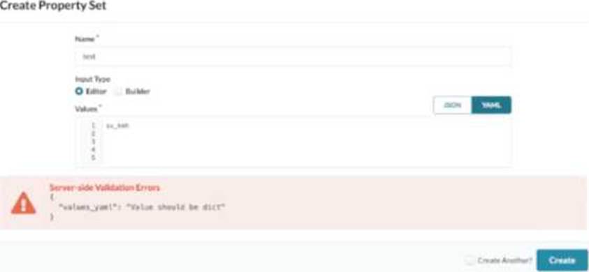
Referring to the exhibit, how would you correct the error?
- A . Use the Builder option for input type of YAML.
- B . Remove the trailing blank lines.
- C . Change to JSON and click Create.
- D . Use valid YAML syntax of key: value.
D
Explanation:
In Apstra 5.1, a property set is a structured data object used to parameterize configlets (config templates). The key point is that Apstra expects the property set “values” to be a dictionary/map so that the configlet can reference variables by name (for example, {{ NTP_SRV1 }} or nested keys). The exhibit shows a server-side validation error indicating that values_yaml “should be dict,” which occurs when the YAML content is entered as a single scalar string (such as try_ksh) instead of a key-value mapping.
To correct this, rewrite the YAML using valid key: value syntax so the top-level structure is a dictionary. For example, a minimal valid property set would look like role: try_ksh (or any meaningful key name aligned to the variables your configlet expects). If multiple variables are needed, add additional keys, and if your configlet uses nested objects, represent them as nested YAML dictionaries. This correction aligns the property set with Apstra’s intent-based model: values are stored as named properties and then rendered deterministically into device configuration. This is independent of Junos v24.4 specifics; Junos becomes relevant when the rendered configlet content is applied to devices, but the property set itself must first validate as a dictionary for Apstra to render the template correctly.
Verified Juniper sources (URLs):
https://www.juniper.net/documentation/us/en/software/apstra5.1/apstra-user-guide/topics/task/property-set-datacenter-design-create.html
https://www.juniper.net/documentation/us/en/software/apstra5.1/apstra-user-guide/topics/concept/property-set-datacenter-design.html
https://www.juniper.net/documentation/us/en/software/apstra5.1/apstra-user-guide/topics/ref/property-sets-api.html
Exhibit.
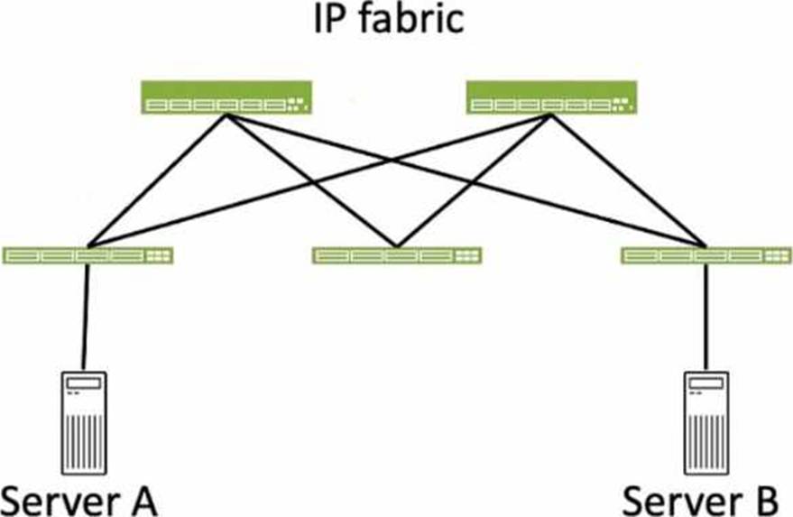
Referring to the exhibit, how many broadcast domains will an Ethernet frame pass through when traversing the IP fabric from Server A to Server B?
- A . 1
- B . 4
- C . 2
- D . 3
C
Explanation:
Referring to the exhibit, the image shows a simplified diagram of an IP fabric network connecting two servers, labeled as Server A and Server B. The IP fabric is a network architecture that uses a Clos topology to provide high bandwidth, low latency, and scalability for data center networks. The IP fabric consists of spine and leaf devices that use BGP as the routing protocol and VXLAN as the overlay technology1.
A broadcast domain is a logical portion of a network where any device can directly transmit broadcast frames to other devices at the data link layer (OSI Layer 2). A broadcast frame is a frame that has a destination MAC address of all ones (FF:FF:FF:FF:FF:FF), which means that it is intended for all devices in the same broadcast domain. A broadcast domain is usually bounded by a router, which does not forward broadcast frames to other networks2.
In the exhibit, there are two broadcast domains that an Ethernet frame will pass through when traversing the IP fabric from Server A to Server
B. The first broadcast domain is the one that contains Server A and the leaf device that it is connected to. The second broadcast domain is the one that contains Server B and the leaf device that it is connected to. The IP fabric itself is not a broadcast domain, because it uses IP routing and VXLAN encapsulation to transport the Ethernet frames over the Layer 3 network. Therefore, the statement C is correct in this scenario.
The following three statements are incorrect in this scenario:
You staged several changes to your Juniper Apstra blueprint but have not committed them.
In this scenario, what is the effect of selecting Revert?
- A . All the staged changes are cleared.
- B . Only the last staged change will be cleared.
- C . The current active configuration will be replaced by the previous active configuration.
- D . A commit is required to complete the revert operation.
A
Explanation:
In Apstra 5.1, blueprint changes follow an intent workflow: you edit intent in Staged, then review the delta in Uncommitted, and finally Commit to activate those changes and create a new revision. If you have staged changes that are visible under Uncommitted but decide not to proceed, the Revert action is used to discard them. Selecting Revert clears the blueprint’s uncommitted intent delta and returns the blueprint to the last committed state (the currently active intended design baseline). In practical terms, it removes all pending edits that were made since the last commit―whether those edits were physical (links/topology), virtual (routing zones, virtual networks), policies (security policies), or catalog-driven operations―so that none of those changes will be deployed.
Revert is not a “single-step undo” limited to only the most recent change; it is a discard of the staged/uncommitted change set. It also does not roll back device configurations on its own (that is handled by revision operations such as Time Voyager rollbacks and subsequent deployment actions). Finally, Revert does not require a commit to take effect; it is used specifically to avoid committing changes. This behavior helps maintain clean operational control in EVPN-VXLAN fabrics by ensuring only validated and intentional intent updates are promoted to the deployed network state.
Verified Juniper sources (URLs):
https://www.juniper.net/documentation/us/en/software/apstra4.2/apstra-user-guide/topics/task/blueprint-commit-revert.html
https://www.juniper.net/documentation/us/en/software/apstra6.1/apstra-user-guide/topics/task/time-voyager-rollback-blueprint-revision.html
You want to make a widget appear on the main dashboard in Juniper Apstr
a. In this scenario, which statement is correct?
- A . When creating the widget, select the Add to Blueprint Dashboard option.
- B . On the blueprint dashboard, click on the Add Widget option.
- C . Widgets automatically appear on the blueprint dashboard.
- D . Set the Default toggle switch to On for the desired widget.
D
Explanation:
In Juniper Apstra, a widget is a graphical element that displays data from an intent-based analytics (IBA) probe. A widget can be used to monitor different aspects of the network and raise alerts to any anomalies. A widget can be viewed by itself or added to an analytics dashboard. A dashboard is a collection of widgets that can be customized and organized according to the user’s preference1.
The main dashboard in Juniper Apstra is the blueprint dashboard, which is the default view that shows the network information and configuration for the active blueprint. A blueprint is a logical representation of the network design and intent. The blueprint dashboard can display the system-generated dashboards, the user-generated dashboards, and the individual widgets that are relevant
to the network2.
To make a widget appear on the main dashboard in Juniper Apstra, the user needs to set the Default toggle switch to On for the desired widget. This will add the widget to the blueprint dashboard, where it can be viewed along with other network information. The user can also remove the widget from the blueprint dashboard by setting the Default toggle switch to Off for the widget3. Therefore, the statement D is correct in this scenario.
The following three statements are incorrect in this scenario:
When creating the widget, select the Add to Blueprint Dashboard option. This is not true, because there is no such option when creating a widget in Juniper Apstra. The user can only select the widget type, the probe, and the display mode when creating a widget4. To add the widget to the blueprint dashboard, the user needs to set the Default toggle switch to On for the widget after creating it3.
On the blueprint dashboard, click on the Add Widget option. This is not true, because there is no such option on the blueprint dashboard in Juniper Apstra. The user can only view, edit, or delete the existing widgets and dashboards on the blueprint dashboard2. To add a widget to the blueprint dashboard, the user needs to set the Default toggle switch to On for the widget from the widgets table view3.
Widgets automatically appear on the blueprint dashboard. This is not true, because widgets do not automatically appear on the blueprint dashboard in Juniper Apstra. The user needs to manually add the widgets to the blueprint dashboard by setting the Default toggle switch to On for the widgets that they want to see on the blueprint dashboard3. The only exception is the widgets that are part of the system-generated dashboards, which are automatically created and added to the blueprint dashboard based on the state of the active blueprint2.
Reference: Widgets Overview
Blueprint Summaries and Dashboard
Widgets Introduction
Create Widget